
OK2BWN radio orienteering receivers come with 5-pin DIN headphone jacks. These are nice because they are durable and are a standard jack.

Unfortunately, most commercial headphones come with a 3.5mm (1/8″) stereo plug. Or, if the headphones include a microphone, they will have a 3.5mm (1/8″) TRRS plug.
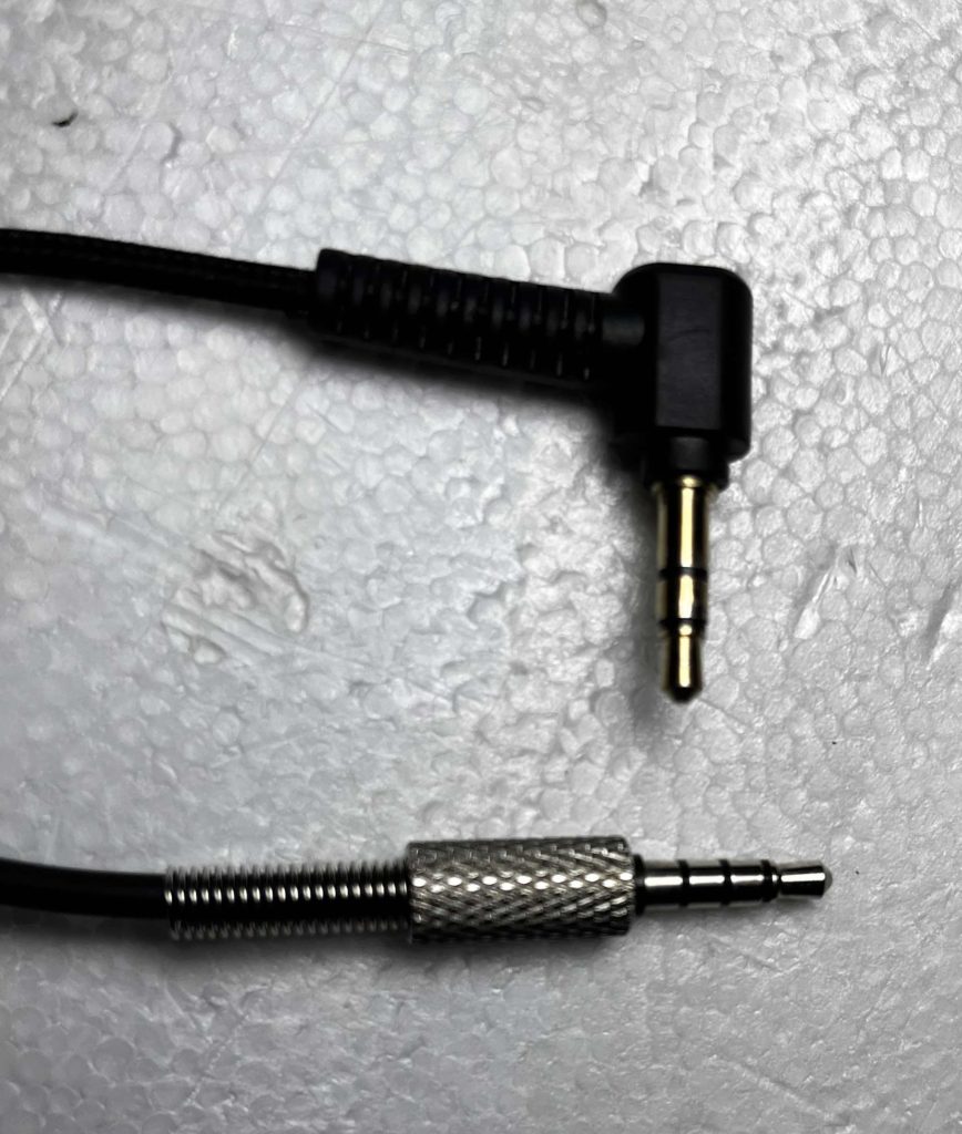
Whether your headphones include a microphone or not, here’s how to get your headphones to plug into your 5-Pin-DIN-jack-equipped receiver and work as they are supposed to.
Figures 1 and 2 below show how headphones are wired to their plugs. If your headphones include a built-in microphone, they use a slightly different audio plug but are wired almost identically.
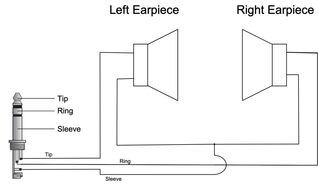
Figure 1: Wiring diagram of most non-microphone headphones
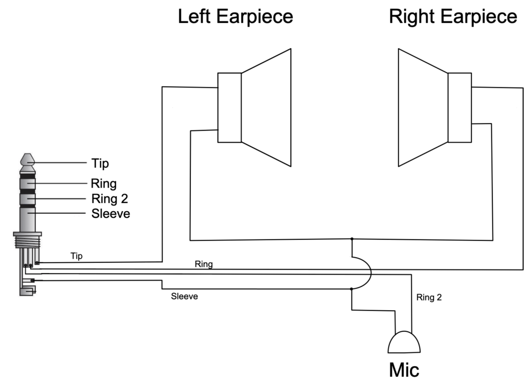
Figure 2: Wiring diagram of most Microphone-equipped (TRRS) headphones
OK2BWN receivers have female 5-pin DIN sockets, which are used for charging, turning the receiver off/on, and providing connections for headphones. Pinouts are available online for all OK2BWN devices. The receivers’ female jack connections are shown in Figure 3.
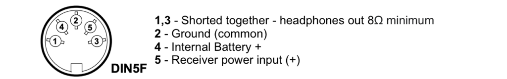
Figure 3: Pinout of the 5-pin DIN jack on OK2BWN receivers
Note the odd numbering order! 1-4-2-5-3 as you go from left to right. Pay close attention when wiring connectors!
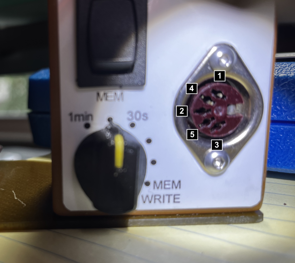
The pinout in Figure 3 is from the perspective of the rear of the jack – the side where the receiver’s internal wires are soldered to it. For wiring the headphones, the direction of view doesn’t actually matter due to the left-right symmetry of the connections. But if you’re using Figure 3 for other purposes, like accessing the internal battery, then you should be aware that pins 4 and 5 locations are reversed when viewing the jack from the front of the receiver.
Regardless of whether your headphones have a microphone, you need to connect the Tip, Ring, and Sleeve wires to the correct pins on a 5-pin DIN plug. In addition, two of the DIN connector’s pins (4 and 5) need to be shorted together to turn the receiver on. Ring 2 should be left disconnected on headphones equipped with a microphone.
Figure 4 below shows what you are trying to achieve. The wiring depicted there connects the left and right earpieces in parallel. Pins 4 and 5 of the plug are shorted together to apply power to the receiver when the headphones are plugged in.
IMPORTANT!
Carefully test all connections using a volt-ohm meter (VOM) or continuity tester before inserting a plug into your receiver. Pay special attention that pins 4 and 5 are not shorted to any other pins. A short circuit could result in excessive current from the receiver’s internal battery – a condition that could destroy the battery and might result in a fire. Never solder a plug while it is inserted into the receiver’s jack.
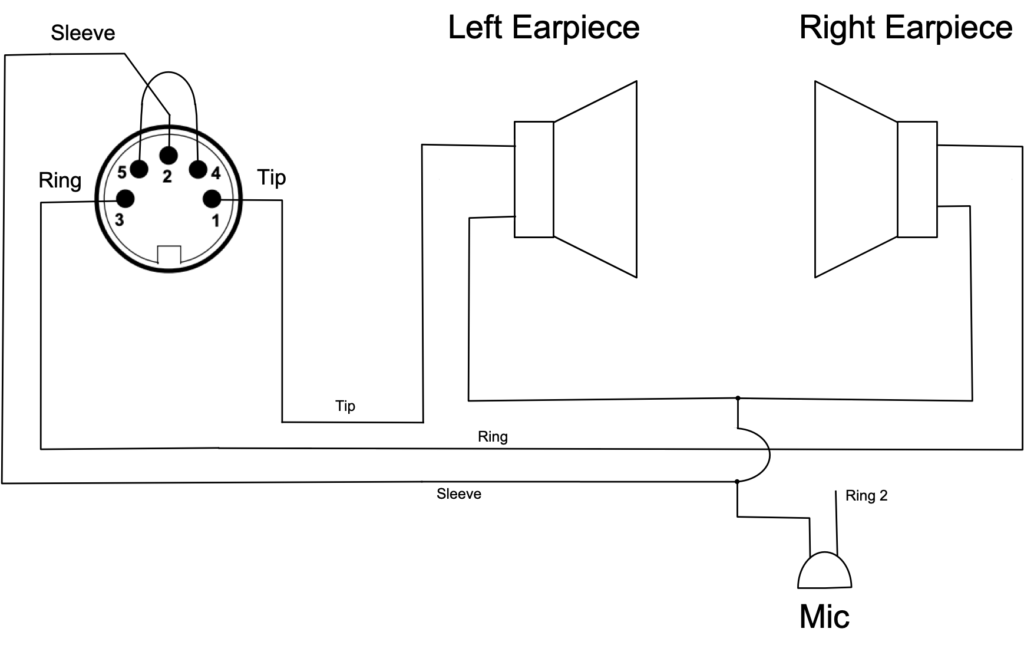
Figure 4: Wiring diagram for connecting a 5-pin DIN male plug.
Note that pins 1 and 3 of the plug will be shorted together (see Figure 3) when inserted into the receiver’s jack. So it isn’t essential to connect the Tip and Ring wires to both pins 1 and 3: connecting both wires to just one of those pins also works. But connecting the two pins separately to pins 1 and 3 provides a little additional reliability: if either plug pin were to fail, one earpiece would still function.
The earpieces of most modern headphones have an impedance of about 32 ohms. So the parallel wiring shown in Figure 4 results in a headphone impedance of about 16 ohms, which is just about right for OK2BWN receivers. You should not use headphones with an impedance of less than 8 ohms with OK2BWN receivers.
The simplest way to accomplish the wiring shown in Figure 4 is to remove the headphones’ 3.5mm (1/8″) plug and replace it with a 5-pin DIN plug, wiring it as shown in Figure 4. But, if you would like to keep your headphones’ 3.5mm plug intact, you need a “3.5mm-to-5-pin-DIN OK2BWN receiver headphone adapter.” I’ve never seen such an adapter sold commercially, so you must make it yourself. But you are in luck: they are not too difficult to build.
Suitable parts to build an adapter are available from Mouser, Digi-Key, and other electronics parts retailers. But you can avoid most of the soldering (and some aggravation) by purchasing a cable assembly on Amazon. If that link didn’t work, search Amazon.com for “3.5mm Female Jack to Bare Wire Open End TRS 3 Pole Stereo“. Be sure to purchase a cable with a stereo female jack on one end (not a plug) that looks like the following image.
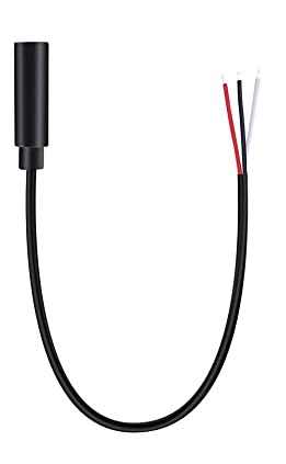
Figure 5: 3.5mm Female Jack to Bare Wire TRS 3-pole Stereo Cable
Now, all you need is a 5-pin DIN plug, which can also be found on Amazon. If that link did not work, search for “5 Pin DIN Male Plug MIDI Cable Connector Soldering.” They are commonly available and often used for MIDI device cables.
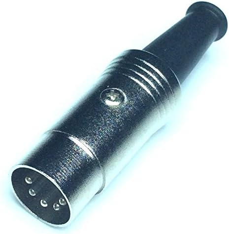
Figure 6: 5-pin male DIN Plug
Soldering is required for the plug shown above. DIN plugs can be a bit tricky to install. Be careful not to overheat any pins as you solder, as the plastic platform that holds them in place can melt. Before soldering the wires onto the pins, remember to slide the rubber sleeve and outer case onto the cable.
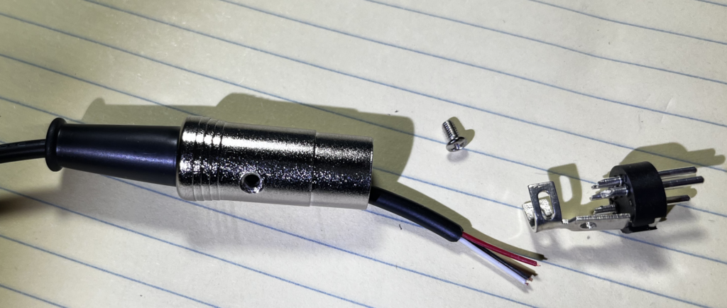
Figure 7: 5-pin DIN plug dismantled – slide the wire through the housing before soldering to pins
Attach the red wire to pin 1, the white wire to pin 3, and the black wire to pin 2. Then run a very short piece of wire connecting pin 4 to pin 5. Slide the outer metal jacket up over the pin platform until the pins are inside the metal shell. Then attach the pins in place using the small screw.
IMPORTANT! SO IT IS WORTH REPEATING
Carefully test all connections using a volt-ohm meter (VOM) or continuity tester before inserting a plug into your receiver. Pay special attention that pins 4 and 5 are not shorted to any other pins. A short circuit could result in excessive current from the receiver’s internal battery – a condition that could destroy the battery and might result in a fire. Never solder a plug while it is inserted into the receiver’s jack.
Using MIDI Cables Instead
If you decide you’d like to avoid soldering a DIN connector, you can purchase a MIDI cable instead, cut it in two, and splice one half onto one of the 3.5mm jack assemblies – remembering to short together the wires running to pins 4 and 5. A reliable splice also involves soldering, but splicing wires is usually a simpler task than installing connectors. Cover the splice with suitable adhesive-lined heat-shrink tubing to protect it mechanically and prevent water intrusion.
You can purchase MIDI cables on Amazon and elsewhere – just be sure the MIDI cable wires connect to all five DIN pins (some do not). A single MIDI cable cut in half will give you two usable DIN-terminated cables for building two headphone adapters. Two commercially built MIDI cables are shown in Figure 8.
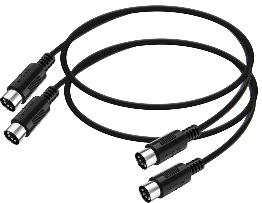
Figure 8: Two sets of MIDI cables that can be cut in two, each providing two professionally terminated 5-pin DIN connector assemblies
The MIDI cables I purchased use the following wire color scheme. Yours might be different, so use an ohm meter to check.
Pin 1: White (Headphone)
Pin 2: Shield (Ground Common)
Pin 3: Black (Headphone)
Pin 4: Yellow (Internal Battery+)
Pin 5: Red (Receiver Power Input+)
Completed Adapters
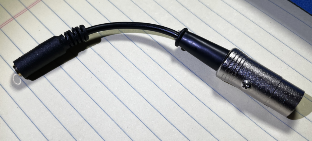
Figure 9: Completed headphone adapter
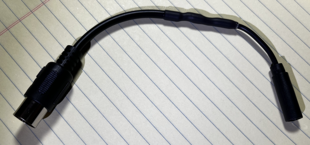
Figure 10: Completed headphone adapter using half of a MIDI cable
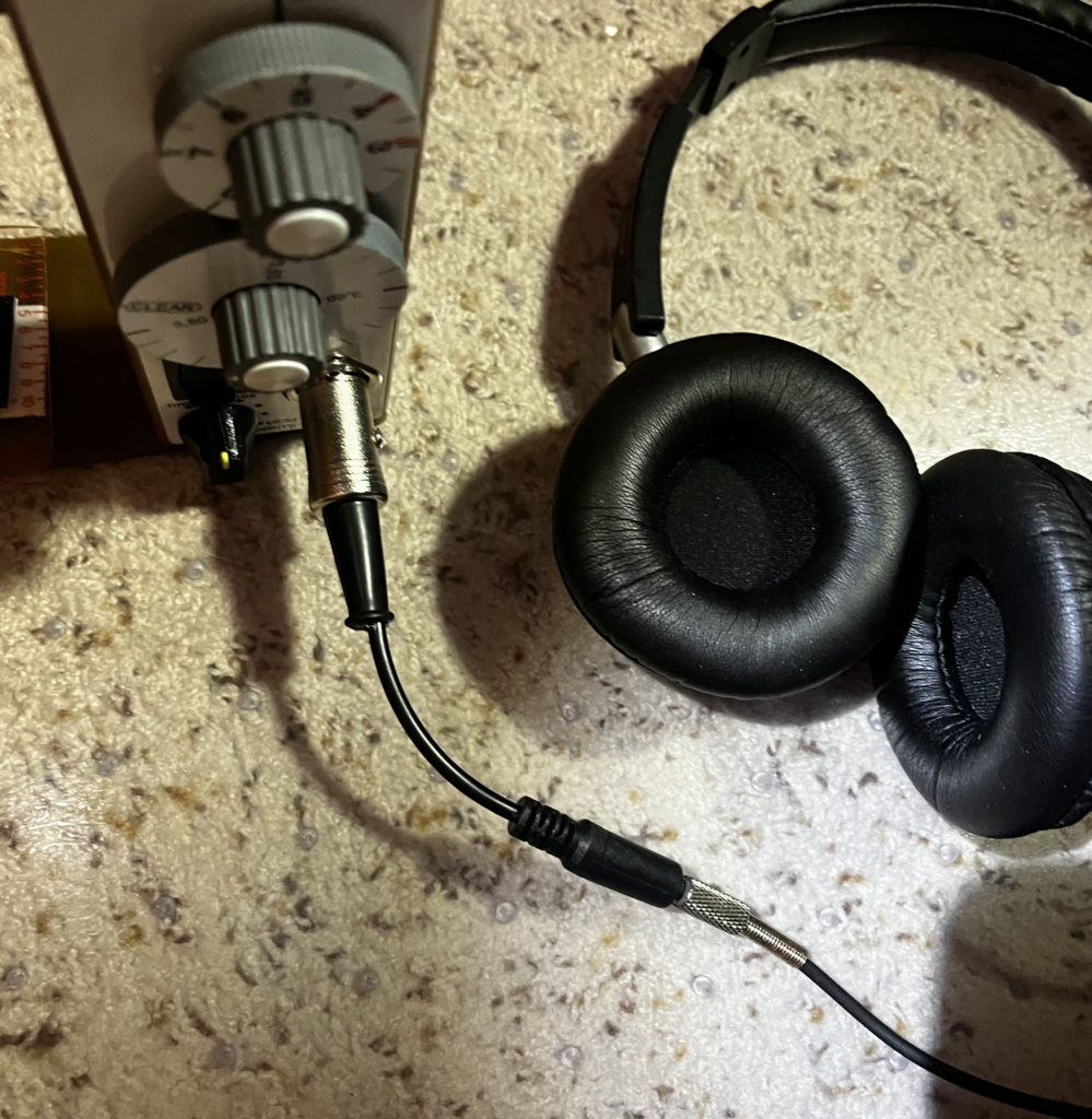
Figure 11: Adapter shown in use with standard commercial headphones
Important: Note that the receiver will be powered on whenever the adapter’s DIN connector is plugged into the receiver’s jack. Failing to unplug the adapter from the receiver will drain the receiver’s battery. It isn’t enough to only unplug the headphones from the adapter!
Keep your shiny new adapter working like new by periodically applying some contact cleaner to the headphone jack and DIN plug.