
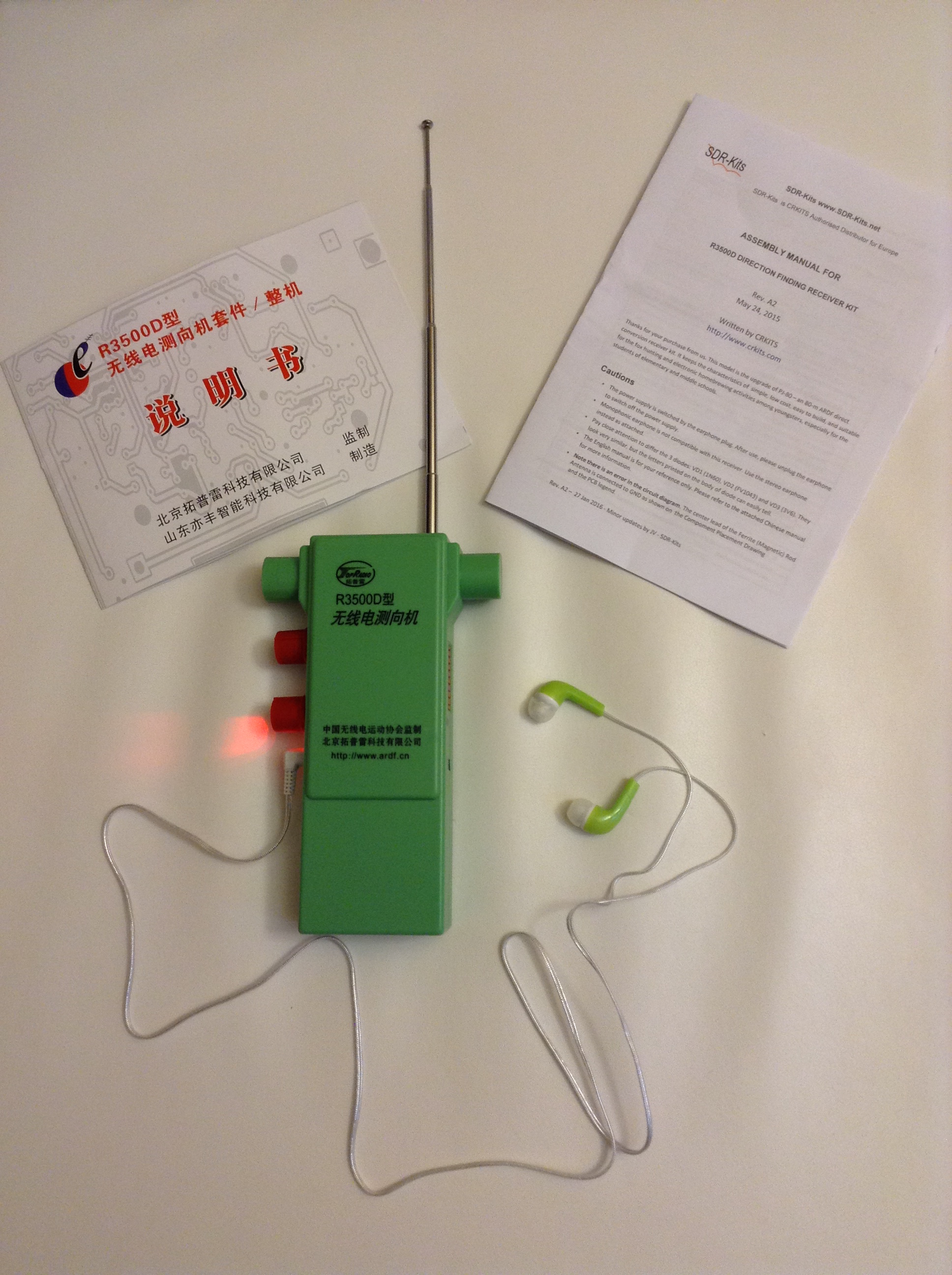
The R3500D is an 80m ARDF receiver capable of covering from 3.5 to 3.6 MHz. It is a reasonable beginner’s receiver for learning ARDF, and affordable with prices starting at $30 for a kit, and $40 for a built and tested unit. For that price don’t expect any bells or whistles. It hasn’t any. Its performance is reasonable, its design is utilitarian, and it gets the job done.
To get a better idea of how it is constructed, I ordered one of the kits and built it using the instructions provided. Details of my experience are described on this page.
I also have purchased several factory-built R3500D receivers. Let me tell you upfront: the factory-built units work better than the kit. They really do. Their design includes improvements to the ferrite rod antenna and a few other tweaks to the front-end design. The result is a much more discernable cardioid pattern when the sense button is pressed. The factory units also use surface mount components, which might improve the reliability and repeatability of the receiver, particularly if higher-precision components are used.
Factory-Built Units
Most of the issues described for the kits also apply to the factory-built receivers. They drift with temperature, exhibit some microphonics, and photosensitivity as described for the kit. But their cardioid pattern, though not perfect, is easily discernable. That is very important for removing the 180-degree ambiguity, and reason enough to opt for a factory unit over a kit.
Factory-built units can be purchased in bulk on Taobao.com, a Chinese online retailer (similar to Amazon or Alibaba). The website is entirely written in Chinese, and browser translation to English doesn’t work as well as one might like on the Taobao website. You may need to use Google Translate, or a similar service if you cannot create an account and place an order without translation help. It can be done, but some patience and tenacity is required. It is definitely worth it if you plan to order ten or more units. Delivery usually takes three or four weeks.
If you want to purchase just one R3500D, you are probably better off contacting SDR-Kits or CRKits and asking if they can sell you a factory-built unit.
Operation
The R3500D is powered on when the headphone plug is fully inserted into the headphone jack – which is typical for most ARDF receivers. Always remember to unplug the headphones when it is time to shut off the receiver.
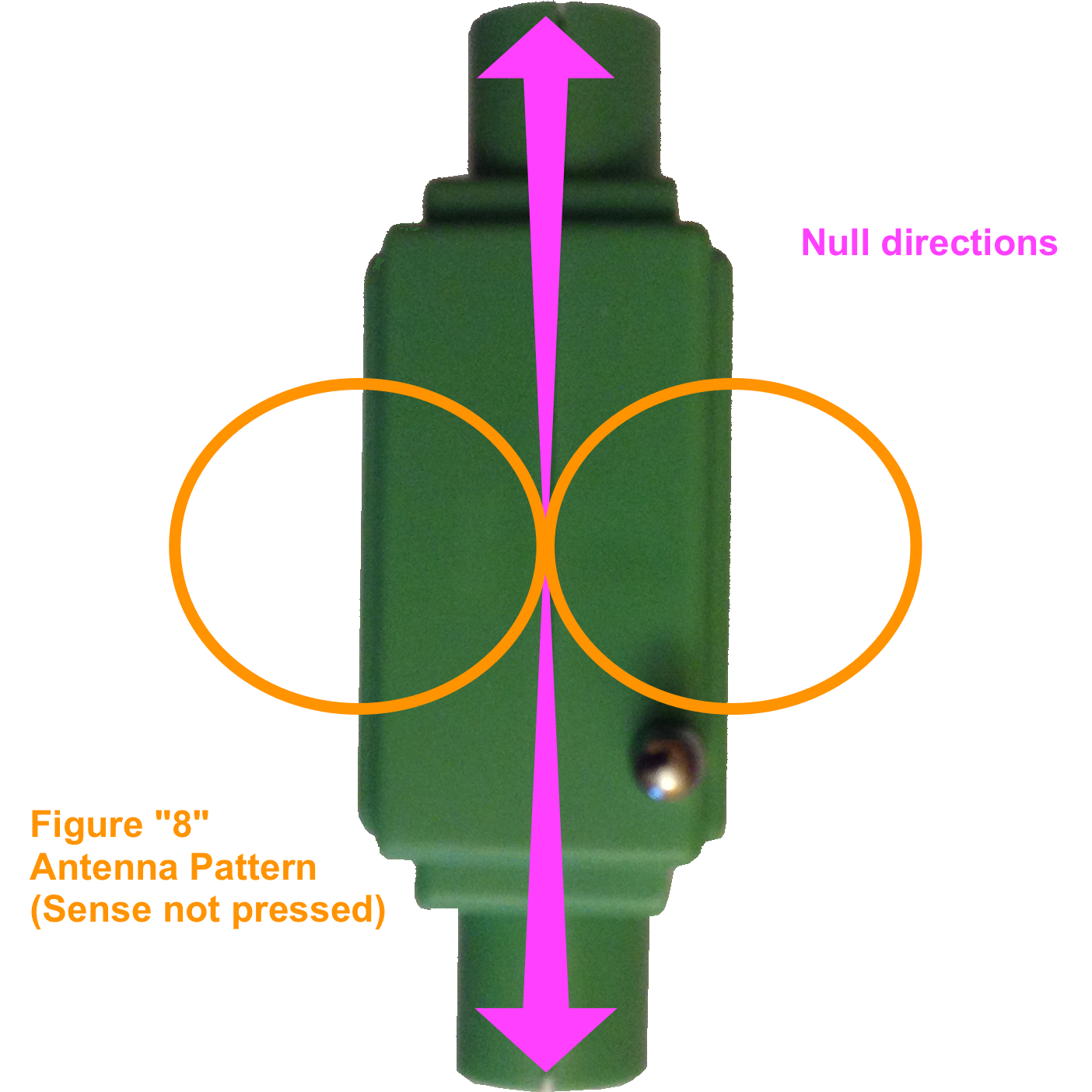
When taking bearings, always hold the receiver upright – that is, with the Sense antenna pointing vertically, perpendicular to the ground. Any other receiver orientation may not provide accurate bearings.
The most precise signal-direction bearings can be achieved using the figure “8” antenna pattern. That is the antenna receiving pattern obtained when you do not press the sense button. To identify a null direction, it is necessary to rotate the receiver around the vertical axis until a precise null (no signal) is heard in the headphones. You will obtain a null at two bearing angles located 180 degrees opposite one another. So the bearing you get is precise but ambiguous: the transmitter might be located in the direction of the null, or it might be located precisely 180 degrees the opposite direction!
The ambiguity of the null-direction bearing can be removed using the Sense antenna. Keeping the receiver oriented vertically, press and hold the red sense button on the side of the R3500D. This changes the antenna pattern to a cardioid shape, which has a peak signal strength in only one direction. The peak direction will agree with the null direction that points toward the transmitter.
The cardioid pattern’s peak is not as precise as the figure “8” null, so for precise bearing measurements, it is best to use the figure “8” null direction. A quick check with the sense button pressed is all it takes to immediately determine which null direction points toward the transmitter.
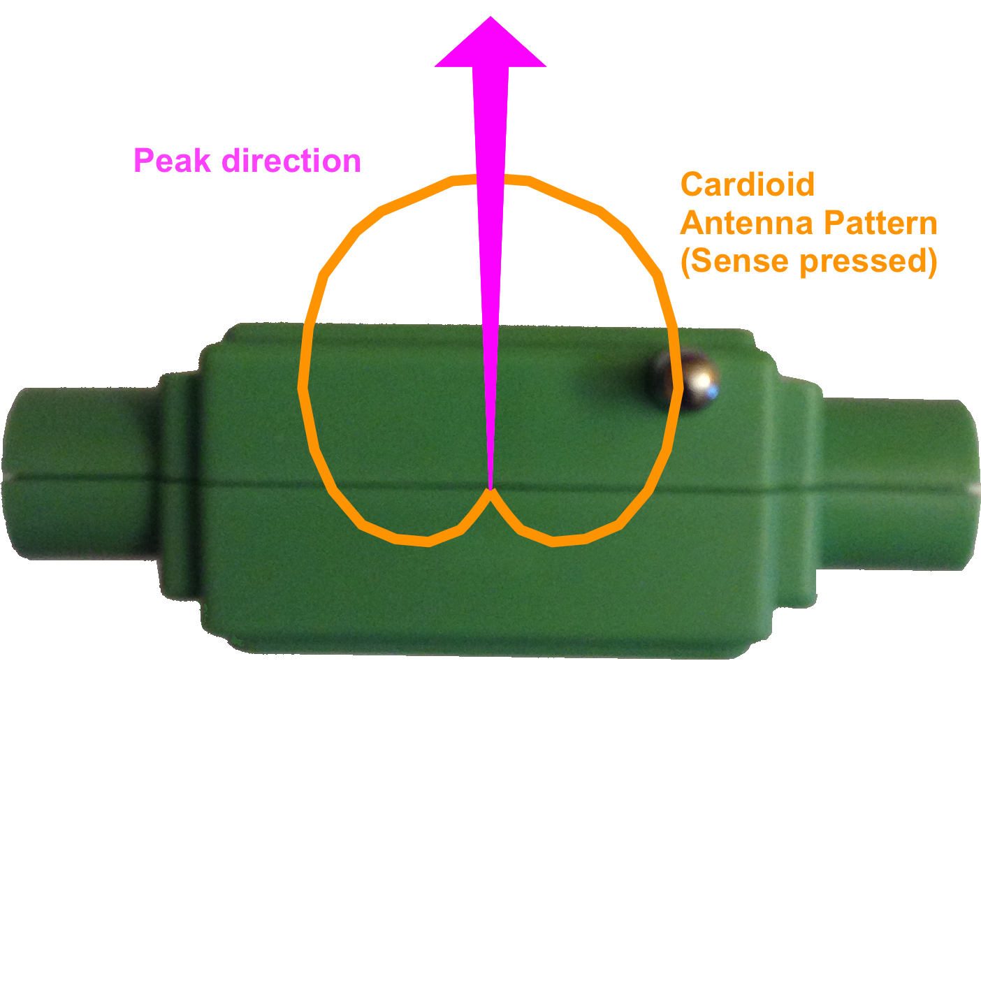
Note that the figure “8” null direction and the cardioid peak direction are oriented 90 degrees apart. This is to say that the R3500D needs to be rotated 90 degrees between taking the figure “8” and cardioid direction readings. That can be a source of confusion when learning to use the receiver. With practice, it will become second nature to rotate the receiver 90 degrees between null and peak direction measurements.
The small ferrite loop antenna does not provide such distinct nulls or cardioid pattern as one would expect from a large tuned-loop antenna. That’s the price to be paid for small size and simplicity.
The cardioid pattern’s null direction proved easier to identify than its peak. The cardioid null direction is always 180 degrees opposite the direction of the peak. So the cardioid’s null can be just as readily used for eliminating the figure “8” ambiguity. To avoid confusion it would be wise to mark on the R3500D’s chassis its orientation when pointing at the transmitter, and whether peak or null should be used for determining the right direction: an arrow labeled “peak” or “null” is all that is required.
The Kit (Not Recommended)
Receiver Documentation
The detailed assembly manual is written in Chinese, so for me, it was only helpful for its diagrams: a schematic and a circuit board parts-placement diagram. A Google Translate-derived translation of the Chinese text was created after construction was complete, and is provided at the bottom of this page. An English version of the assembly manual was also included with the kit, and it seems that the English language manual includes all the essential construction details from the Chinese version.
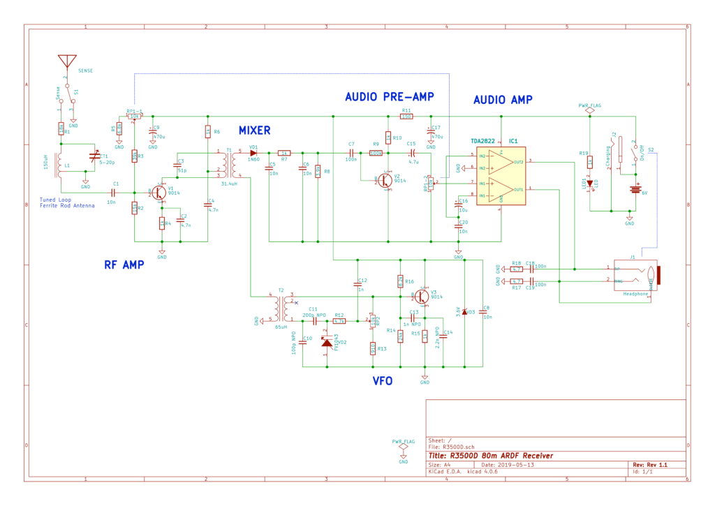
Some errors were found in the official schematic. A corrected schematic diagram, true to the traces on the circuit board, is provided below. Just click on the image to view a PDF version that can be downloaded.
Receiver Design
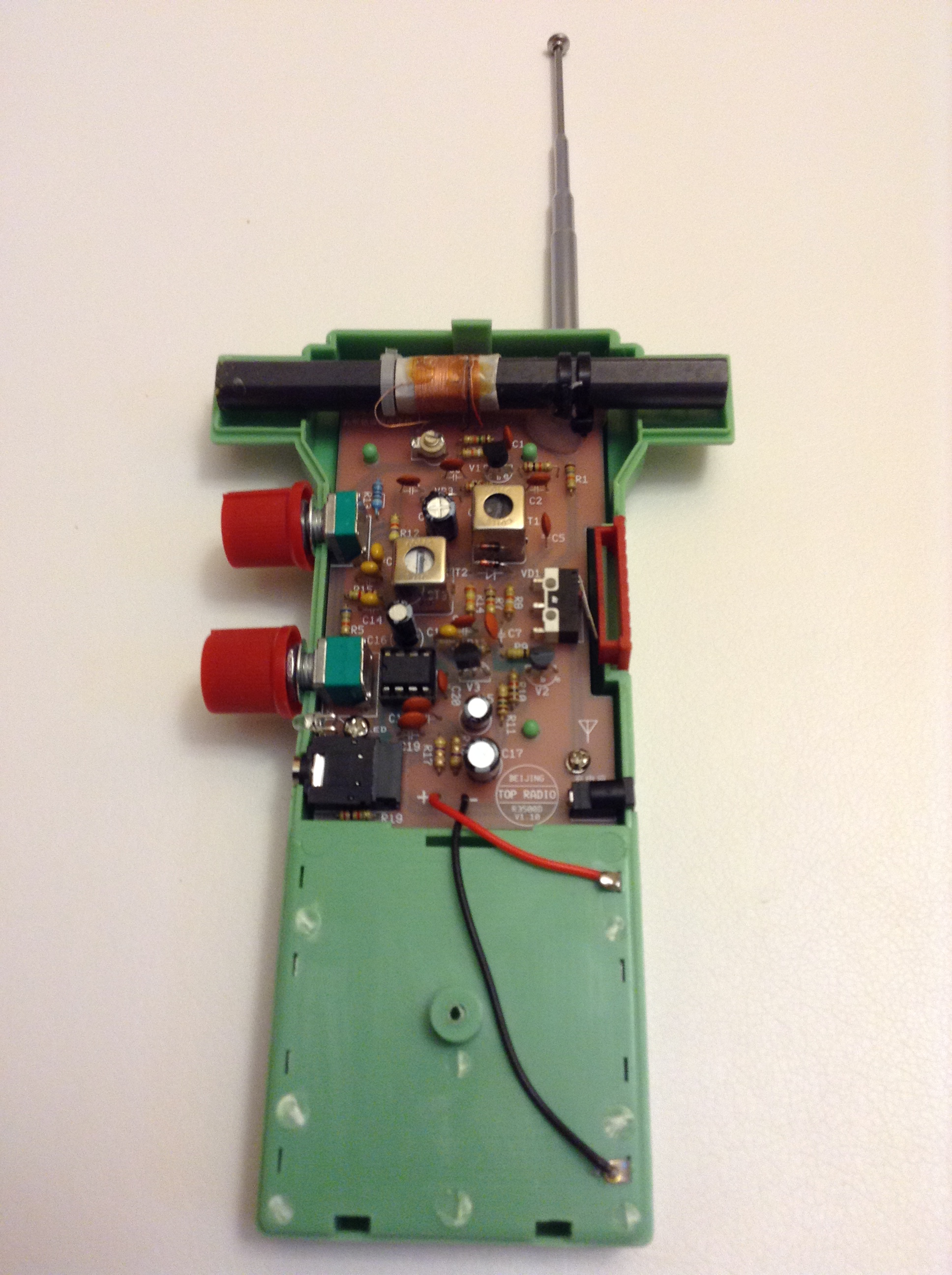
The simplicity of the R3500D is evident from the schematic. The entire receiver consists of about 50 discrete components and a single audio amplifier integrated circuit. Everything mounts to a single-sided printed circuit board that measures 9.7 cm x 5.3 cm.
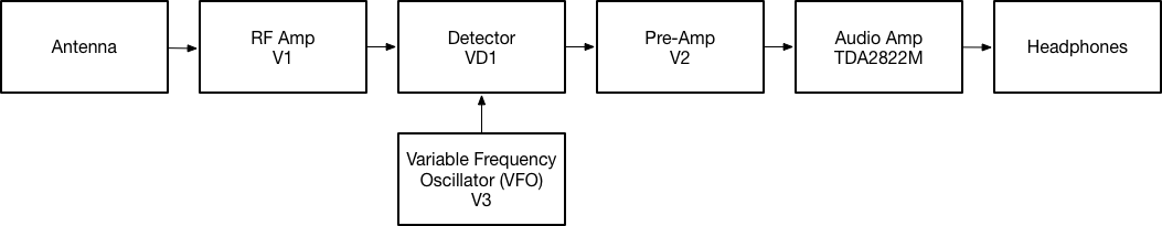
The R3500D is a direct-conversion receiver design, meaning there is a single down-conversion step from RF to audio. A varactor-tuned variable frequency oscillator (VFO) provides the local oscillator signal that mixes with the RF signal. An interesting design choice was to have the VFO provide a signal that is at half the received frequency: 1.75 MHz to 1.8 MHz VFO-out for 3.5 MHz to 3.6 MHz received signal band coverage. (Ordinarily, a 3.5 MHz to 3.6 MHz VFO frequency range would be used in such a design.) The half-frequency approach appears to work because of the simple mixer design (a single germanium diode), which generates a host of VFO products, including a strong second harmonic of the VFO. This choice for VFO tuning range might have been made in order to improve VFO stability, or to reduce the amount of in-band radiated receiver emissions, or due to other considerations. Regardless, the design works, so there are no complaints!
Directionality is achieved using a “Tuned Loop plus Sense Antenna” design. The tuned loop provides an azimuthal directional pattern that looks something like a figure “8”. When that figure “8” pattern gets combined internally with the signal arriving from the whip Sense antenna, the directional pattern becomes a cardioid, with only one preferred (i.e., stronger) signal direction. More about how this works in practice is provided later in this discussion.
The 80m tuned-loop antenna consists of a 150 uH inductor wound on a ferrite rod. Capacitor CT tunes the inductor to resonance on the 80m band. The Sense antenna is a telescoping whip that collapses into the plastic case. Fully extending the whip antenna seems to result in the best cardioid pattern.
The English language assembly manual consists of just six pages that include a color photograph of an assembled circuit board and a complete parts list. Despite its brevity, the English assembly manual proved very helpful during the assembly and alignment processes.
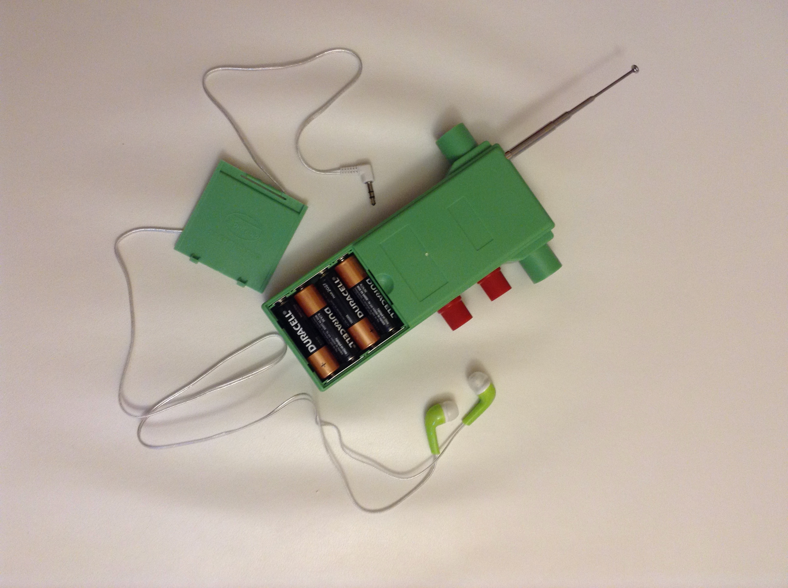
The earphones provided with the R3500D were a pleasant surprise. They are comfortable, provide good audio, and appear to be reasonably sturdy. Note: the R3500D requires the use of stereo headphones, or at least a stereo audio plug. Earphones with monophonic plugs (two conductors) must have their plugs replaced with stereo plugs (three conductors) in order to avoid damaging the audio amplifier.
The plastic chassis seems rugged enough to withstand moderate abuse. It is not the least bit water resistant, so the R3500D must be protected from rain.
Assembly
The English instructions provided with the R3500D were adequate for completing the kit. Alignment instructions were a little vague. Using a digital oscilloscope or frequency counter to measure the VFO frequency simplifies the VFO alignment process considerably.
The kit went together quickly and easily. For most builders, it should prove to be a true weekend project. All the correct parts in the right quantities were included. No components were missing or damaged.
A microscope proved handy for examining solder joints, and for visually identifying parts – particularly the diodes.
An LCR meter gave additional assurance that the parts were not defective and that their values had been correctly identified. No defective parts were found in the kit I received.
Note: After installing R1 be sure to trim its lead wires close to the surface of the PCB, leaving little of the leads extending below the board. The telescoping antenna will pass directly under those leads. If they are long enough they can slice a hole in the insulating sleeve protecting the antenna, and short it out. No damage to the receiver’s components will result from the short, but the sense function will not work properly.
Alignment
Alignment instructions call for a voltmeter and an RF signal generator or a transmitter. But I found that a digital oscilloscope makes VFO alignment go much faster.
Attaching a scope probe to the anode of VD1 allowed me to view the VFO output signal. The O-scope’s frequency measurement feature allowed me to read the approximate VFO frequency and adjust it (using the T2 slug) so that it went between 1.75 MHz and 1.8 MHz as the potentiometer RP2 traveled between its limits.
An 80m signal source is essential for adjusting CT and T1 for maximum receiver sensitivity. Listening to the received signal strength in the headphones was all that was required to adjust CT and T1.
Improvements
A few small issues discovered during assembly are discussed and illustrated below.
Ferrite Rod Tilt
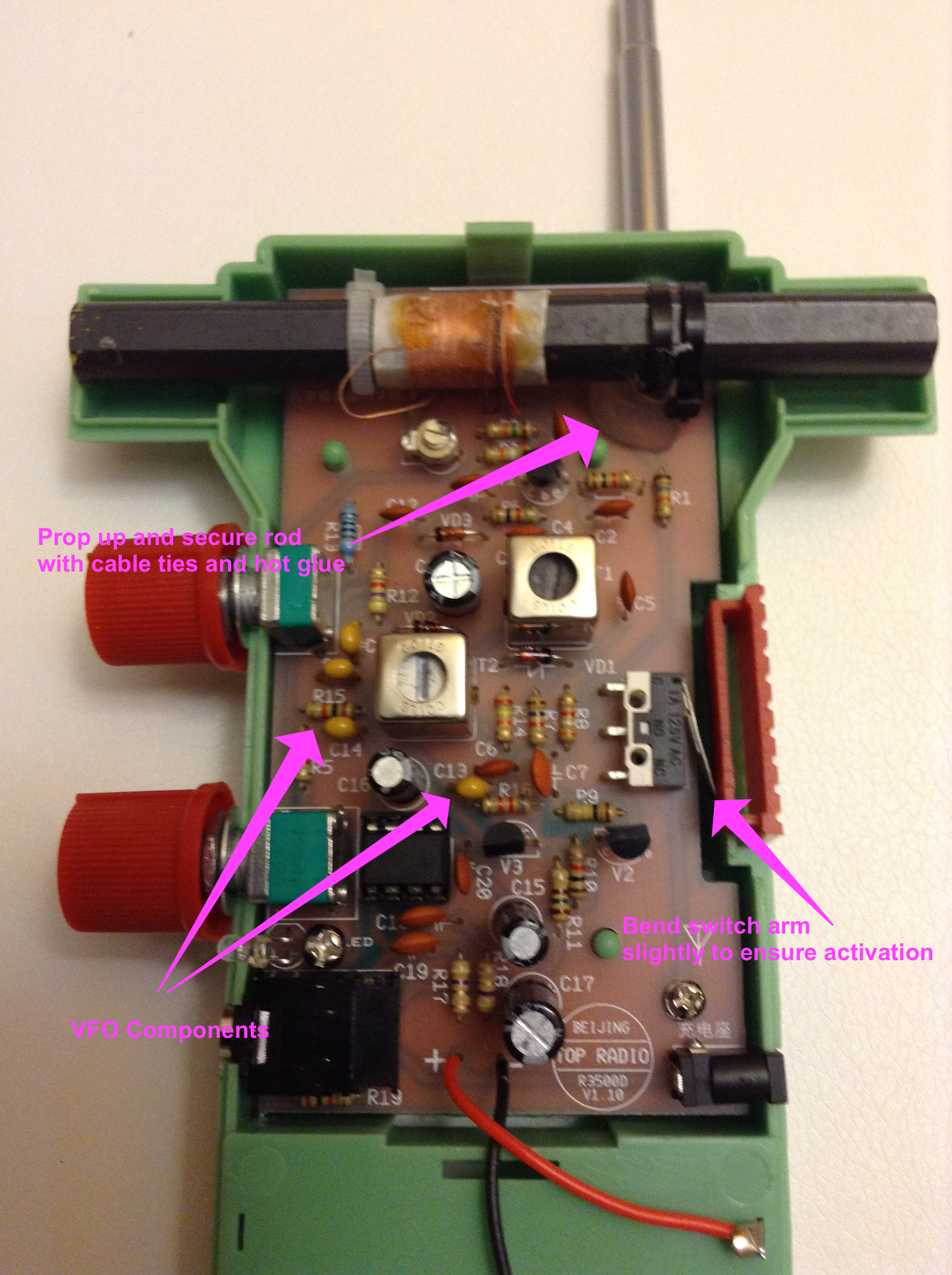
Instructions called for the ferrite rod to be secured only by a single cable tie attached to the PCB. This left the rod tilted by about 10 degrees with respect to the face of the receiver. Left uncorrected the tilt could result in a pointing error when measuring bearings using antenna null headings. To better secure the rod and to remove the slight tilt, the cable tie was removed and the ferrite rod was hot glued directly to the circuit board.
Note: Initially, the rod’s tilt was corrected by propping it up with additional ties and hot glue (see below). But that solution could cause the ferrite rod to touch the front shell of the plastic case when fully assembled. Rod contact with the case resulted in vibrations propagating from the case to the ferrite rod and the circuit board, degrading frequency stability. Frequency stability improved markedly when the ferrite rod was given a lower profile by gluing it directly against the front of the circuit board.
Sense Switch
Initially, the Sense antenna switch would not activate when the sense button was pressed. This issue was easily resolved by bending the sense switch arm slightly outward.
Filing the top and bottom edges of the red plastic button, to provide more clearance between the button and the recessed chassis button compartment, made the button operate more reliably. About 0.5 mm of material needed to be removed from the top and bottom edges to ensure that the red button could not get stuck.
VFO Drift
The VFO drifts noticeably with ambient temperature fluctuations or in response to chassis flexure and vibrations. The supplied “monolithic” capacitors (yellow color) presumably have better temperature coefficients than the standard ceramic disk capacitors used elsewhere in the design. But additional improvement might be achieved with COG NPO or silver mica components for C10, C11, C13, and C14. T2 is also susceptible to value fluctuation with temperature change, and there is no simple substitute for that component. Placing some insulating material around T2 might slow the effects of temperature change, but would not eliminate the drift.
Placing shielding inside the chassis around the VFO components made no improvement to the frequency stability. A tight grip on the radio, thumping the chassis, or twisting it slightly can cause the frequency to shift by several hundred Hertz. A cure for this behavior will likely require mechanical changes to the PCB or to the chassis design. Reducing board flexure, or isolating the VFO components from the effects of vibrations and flexing, should improve matters.
Although VFO frequency changes are readily observed, they are a distraction but not a major problem. They mostly occur when using the sense button – or any action that applies pressure to the outside of the R3500D chassis. The R3500D remains a usable receiver despite these effects. But the frequency jumps can add confusion to the task of determining cardioid directionality. Occasional adjustments of the tuning dial are required to compensate for its vulnerabilities to temperature and vibration.
PHOTOSENSITIVITY
When testing the R3500D in bright sunshine with the front chassis shell removed, it was observed that the receive frequency would jump suddenly by 100 Hz or so. Then it would jump back. The jumps didn’t appear to have anything to do with the vibration or flexure of the R3500D chassis. Eventually, it was discovered that the jumps would occur as the receiver went into and out of a shadow!
When the R3500D chassis is fully assembled with both shells firmly closed, no direct sunlight should reach the diodes. But in brilliant sunlight, the inside of the chassis will be illuminated by light passing through the thin plastic walls. That is enough to cause noticeable frequency jumps when passing through the shadows of trees.
The root cause? The glass-shell diodes (VD1, VD2, and VD3) are sensitive to light. Their properties, in particular, the capacitance across VD2, vary depending on the amount of ambient light reaching the diodes. The problem is readily solved by covering each of the diodes with an opaque substance. I used a small amount of tacky poster putty, but anything opaque and non-conductive will do the job. A dab of opaque glue, or paint fully covering each diode, should work just fine.
Volume Level
The receiver draws about 35 mA of current from the AA batteries at moderate headphone volume levels. If the volume is cranked up loud (and it can get very loud), the current draw goes up well over 100 mA when a strong signal is received.
There are not separate “volume” and “gain” adjustments. RP1 is a ganged dual potentiometer: one pot adjusts RF gain, and the other, audio gain. A single knob to accomplish both tasks makes the receiver operation simpler. It also means that high volume levels must be used when the received signal is weak. This can cause problems if the receiver is used in a noisy environment, where one might wish to increase the audio gain without affecting the RF gain.
LED Current
The red LED glows continuously whenever the receiver is powered on. Several mA could be saved by placing a capacitor (~1uF) between R19 and the LED. This would cause the LED to flash once when the headphone plug is inserted, and then remain off for the remainder of the time. Simply removing the LED would also be acceptable, though it would leave the receiver with no visual indication of sufficient battery voltage and a small hole in the chassis.
Sense Antenna Length
Once the optimum length for the Sense antenna is determined, it should not change. So it is desirable to provide a means for properly extending the telescoping whip to the correct height without having to repeat the trial-and-error alignment process. I haven’t come up with a simple way to do that while still allowing the antenna to fully retract. Any ideas?
Compass Compatibility
The R3500D is not strongly magnetic, but it will deflect a magnetic compass placed in close proximity to the receiver. The telescoping antenna, I was surprised to discover, has a negligible effect on a compass. Nevertheless, a compass mounted directly to the plastic case can deflect by 15 degrees or more. So it is best to mount a reverse-rose compass on a platform that keeps the compass at least 15 cm from the receiver.
Charging Connector
The R3500D includes a battery-charging jack located just below the sense button. The jack connects directly across the 6V battery pack. The jack requires a barrel plug of size 1.3mm ID x 3.5mm OD.
NiCd or NiMH AA cells could probably be safely charged in the R3500D with a proper charger for 4-cell battery packs. But generally, if you use rechargeable batteries, you should plan to remove them from the unit and place them in an appropriate charging device designed for the battery chemistry you are using. Improper charging can result in fire. Never use a NiCd charger for NiMH batteries. And, of course, never attempt to charge alkaline or other non-rechargeable batteries.
The charging jack also provides easy access for measuring the battery voltage without the need to open the battery compartment or remove any batteries. But a suitable plug needs to be used to access lines for voltage measurements.
By removing all batteries from the R3500D the charging jack could be used with an external 6V battery to power the receiver.
Availability
At the time of this writing, kits could be ordered from SDR-Kits, and assembled units are available from CRKits.
Translations
Google Translate on an iPhone was used to obtain the following translations of the Chinese text on the box containing the R3500D kit:
[FRONT OF PACKING BOX]
YiFeng
Radio Direction Finder Kit
Youth Radio Direction Competition
State Sports General Administration, Ministry of Education, China Association for Science and Technology, China Youth Federation,
Central Women’s Federation, All-China Women’s Federation
Beijing Tuopulei Technology Co., Ltd. Production
Shandong YiFeng Intelligent Technology Co., Ltd. Manufacturing
[BACK OF PACKING BOX]
Introduction to Radio Direction Finding
Radio Direction Finding is a science and technology sport that combines modern radio technology with traditional hide-and-seek games. Participants hold radio direction finder to measure the location of the hidden stations in beautiful environments such as jungles and parks, and find them one by one quickly and accurately. Find a lot of stations, and use less time to win. The R3500D type direction finder is suitable for all kinds of schools, especially the medium and primary schools to carry out short-distance 80-meter range direction-finding activities. It is the annual national youth radio direction-finding tournament (National Sports Bureau, National Ministry of Education, China Association for Science and Technology, Communist Youth League) The Central Committee and the All-China Women’s Federation jointly sponsored the use of equipment to participate in radio direction-finding activities, and learned electronic knowledge and production skills. Together with outdoor operations and running to find a platform, it fully embodies theory and practice, hands-on and brain, indoor and outdoor physical fitness. Smart combination. It is a spiritual integration of technology, fitness and entertainment, independent thinking and analysis and judgment, and promotes the comprehensive development of moral, intellectual, aesthetic and labor activities in line with the central government’s awareness of the popularization of technology among adolescents and the implementation of the National Fitness Program. Received the attention of the school, won the support of parents and the love of young people.
[PCB Front Silkscreen Top]
Beijing Topley
www.ardf.cn
[PCB Front Silkscreen Bottom Right]
Beijing OP Radio R3500D V1.10 (in English)
Charging Stand
[FRONT OF THE D3500D CHASSIS]
R3500D Radio Direction Finder
China Radio Sports Association
Produces: Beijing Tuopulei Technology Co., Ltd.
http://www.ardf.cn
[SENSE BUTTON LABEL]
Unidirectional
Instruction Manual
R3500D type radio direction finder kit / complete device
[INSIDE COVER]
DESCRIPTION:
The graphical symbols and text in the circuit diagram of the device conform to the current national standard symbols, which is helpful for teaching students accurate and practical knowledge. Taking into account the connection with the past products, some text symbols and are prompted as follows (non-standard symbols in parentheses): pole tube (BG), diode VD (D), double winding transformer (B), switch S (K), Antenna w (A), the sliding-contact potentiometer RP (W) socket.
PRECAUTIONS
Note 1: The power switch is controlled by the headphone plug. After use, the headphone plug must be unplugged to cut off the power.
Note 2: The use of monophonic headphones with this receiver is prohibited. Otherwise, the internal circuitry could be damaged.
Note 3: This device has a total of 19 resistors and 21 capacitors (including 4 electrolytic capacitors). The capacity of some of the capacitors is represented numerically: the first and second digits indicate those specific digital values, and the third digit indicates the number of zeros to be added at the end. 101 indicates 10 followed by one zero (i.e., 100 pF), 102 indicates 10 followed by two zeroes (i.e., 1000 pF or 0.001 uF), 104 means 10 followed by 4 zeroes (100000 pF or 0.1 uF), 222 means 2200 pF (0.0022 uF).
Note 4: In the kit, detector diode VD1 (1N60), variable capacitance diode VD2 (FV1043) and the Zener diode VD3 (3V6) are all small glass-shell diodes. The end with the black band is the cathode. Their appearance is very similar, so please pay attention to the markings on the glass before installing them.
[PAGE 1]
This device is an upgraded version of the PJ-80 model, retaining the original PJ-80 simple circuitry, low price, and easy construction. The use of a special low-level circuit significantly improves the signal-to-noise ratio of the repeater to improve the sensitivity and dynamic range of the whole receiver. It is suitable for the assembly and use of the majority of young people, especially middle and secondary school radio direction finding and engineering activities.
First, the main performance requirements of the receiver include:
1. A minimum frequency range of at least 3.5 – 3.6 MHz
2. Sensitivity/receivable distance: T3500B series DF transmitter with matching vertical antenna is not less than 600m.
3. Directionality: the direction resolution distance is less than 3m.
4. Power: DC 6V (4 AA batteries)
Second, the circuit block diagram
1. Block Diagram
2. The full circuit schematic diagram and printed circuit board diagram are shown in Figure 1 and the drawing.
[PAGE 2]
Third, the assembly instructions
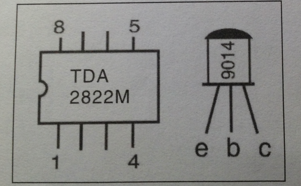
1. Inspection and assembly of components: Carefully inventory all of the components before beginning to solder. Check the quantity, values and quality of the pieces. Confirm that the electrolytic capacitors are not leaking or dry; That transformers T1 (black), T2 (white) are not open; Whether the diodes and transistors test OK. Pay close attention to the correct orientation when installing TDA2822M in its socket.
2. Installing and Securing the Ferrite Rod
Connect the ferrite rod and its coil sleeve as indicated on the printed circuit board silkscreen. Use the white nylon cable tie to secure the ferrite rod onto the PCB.
3. Installing the Telescoping Sense Antenna
Insert the telescoping antenna into the hole at the top right corner of the case, and fasten it with the screw and washer. The washer should be placed between the screw and the PCB.
4. Installing Battery Wires
Only install battery wires after all the PCB components are soldered and checked. Make sure that you connect the wires with the correct battery polarity as indicated on the PCB silkscreen.
[PAGE 3]
Fourth, circuit debugging
1. DC Voltage Checks
(1) Voltage across the Zener diode VD3: 3.5 – 4.4V
(2) V1 bias: the voltage across R4 should be 0.4 – 1V (potentiometer RP1 set to maximum gain position, the collector current of V1 will be 0.4 – 1mA)
V2 bias: the voltage across R10 should be 1.5 – 3V (the collector current of V2 will be 1.5 – 3 mA)
V3 bias: the voltage across R15 shall be 2 – 2.5V (the collector current of V3 will be 2 – 2.5 mA)
Because the R3500D design takes into account normal component variations, there is no need to adjust the bias settings.
2. Variable Frequency Oscillator Alignment
(1) Using an RF signal generator
(a) Turn RP2 fully counterclockwise, the back clockwise a little.
(b) Set the signal generator between 3.5 – 3.6 MHz continuous unmodulated carrier, at a high output level. Connect the output of the generator across a small loop of wire, and place the wire loop over the ferrite rod.
(c) Change the output frequency of the signal generator across a broad range of frequencies until a beat tone is heard in the receiver earphone, this indicates that the local oscillator is working properly. Set the signal generator frequency to 3.55 MHz, then turn the slug of coil T2 (white) until the beat tone is heard again at an audio frequency of about 1000 Hz.
(d) Turn potentiometer RP2 fully clockwise. Adjust the signal generator frequency upward until the beat tone is heard again. Tweak the slug setting of T2 until 3.5 MHz and 3.6 MHz signals are received at RP2 settings that are equally near the edges of its range.
[PAGE 4]
(e) If the receiving coverage is too wide, replace R13 with a greater value. If coverage is too narrow, replace R13 with a smaller value.
(2) Using an 80m Fox Transmitter
(a) Set potentiometer RP2 to the center position;
(b) Turn on the fox transmitter (3.55 or 3.54 MHz). Place the R3500D close to the transmitter antenna;
(c) Turn the slug of T2 until a beat tone is heard, fine tune it to make the tone a pleasant frequency (about 1000 Hz).
(d) Set the fox transmitter to 3.5 and 3.6 MHz, turning potentiometer RP2 to receive the fox signal. If only one signal of 3.5 or 3.6 MHz can be received, fine tune the slug of T2 (see the previous section).
(e) If the receiving coverage is too wide, replace R13 with a greater value. If coverage is too narrow, replace R13 with a smaller value.
3. Antenna Tank Alignment
Receive a signal of 3.53 MHz from a signal generator or transmitter. Fine tune capacitor CT to peak the signal strength. If no peak can be obtained, change the position of the coil on the ferrite rod, then fine tune CT again.
[PAGE 5]
4. RF Amplifier Tank Alignment
Receive a signal of 3.57 MHz from a signal generator or transmitter. Fine tune the slug of T1 (black) to peak the signal strength in the earphone. If no peak can be obtained but the volume is still increasing towards the extreme counterclockwise position of the T2 slug setting, replace capacitor C3 with a smaller value. If no peak can be obtained but the volume is still increasing towards the extreme clockwise position of the T2 slug, replace C3 with a greater value.
5. Directivity Alignment
Select an open field far away from power lines and obstructions. Set a fox transmitter with a vertical antenna. stand at a point 20-50 meters from the fox antenna. Test the figure “8” antenna directivity pattern. (The two null points of some receivers sound a little different, a clearer one should be used for bearings.) Then press button S1 to engage the vertical antenna to obtain a cardioid pattern. Adjust the length of the telescoping antenna to optimize the cardioid pattern, remembering which side of the receiver is facing the transmitter to obtain the peak. If the cardioid pattern cannot be heard clearly, try changing the value of R15 and test again. The minimum distance for which a cardioid pattern can be achieved is approximately 3 meters.
* The R3500D has a charging socket for charging rechargeable batteries. You don’t have to take out the batteries for charging. However, there is no charging or protection circuit built in, so please make sure the charger can match the voltage, polarity and type of the rechargeable batteries.