
Dipole Antenna Design
The goal of this project is to create an easy-to-build design for an 80m transmitting antenna with the following features:
- No radials
- Readily-available inexpensive parts
- Lightweight
- Tunable over the full 80m ARDF frequency range (3.51 MHz – 3.6 MHz)
- Vertical polarization
- Easy set-up and take-down
- Adequate efficiency
- Simple
- Rugged
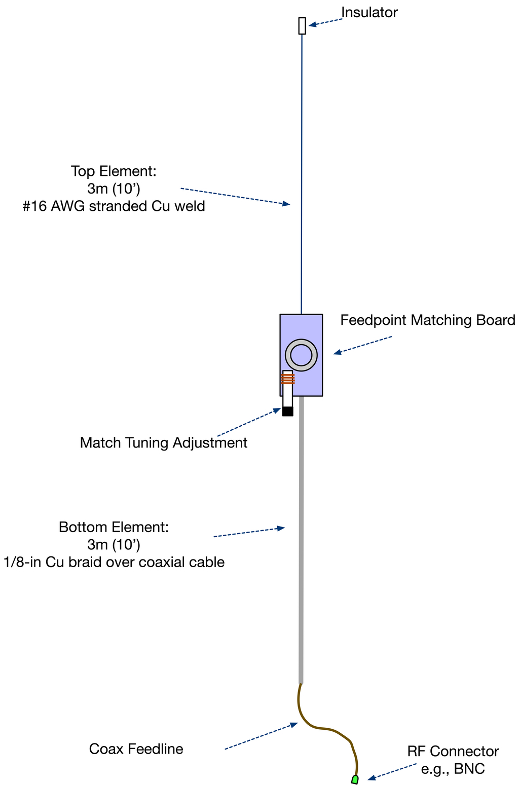
The design is a short vertical dipole (SVD) antenna, with a resonant matching network at its center feedpoint. The coax feedline runs up the center of the bottom antenna element and is shielded by it. The result is a “rope antenna” about 6.1 meters (20 feet) in length. Simply suspend the top end of the antenna six meters above the ground, and plug the other end into an 80m transmitter, and the fox setup is complete.
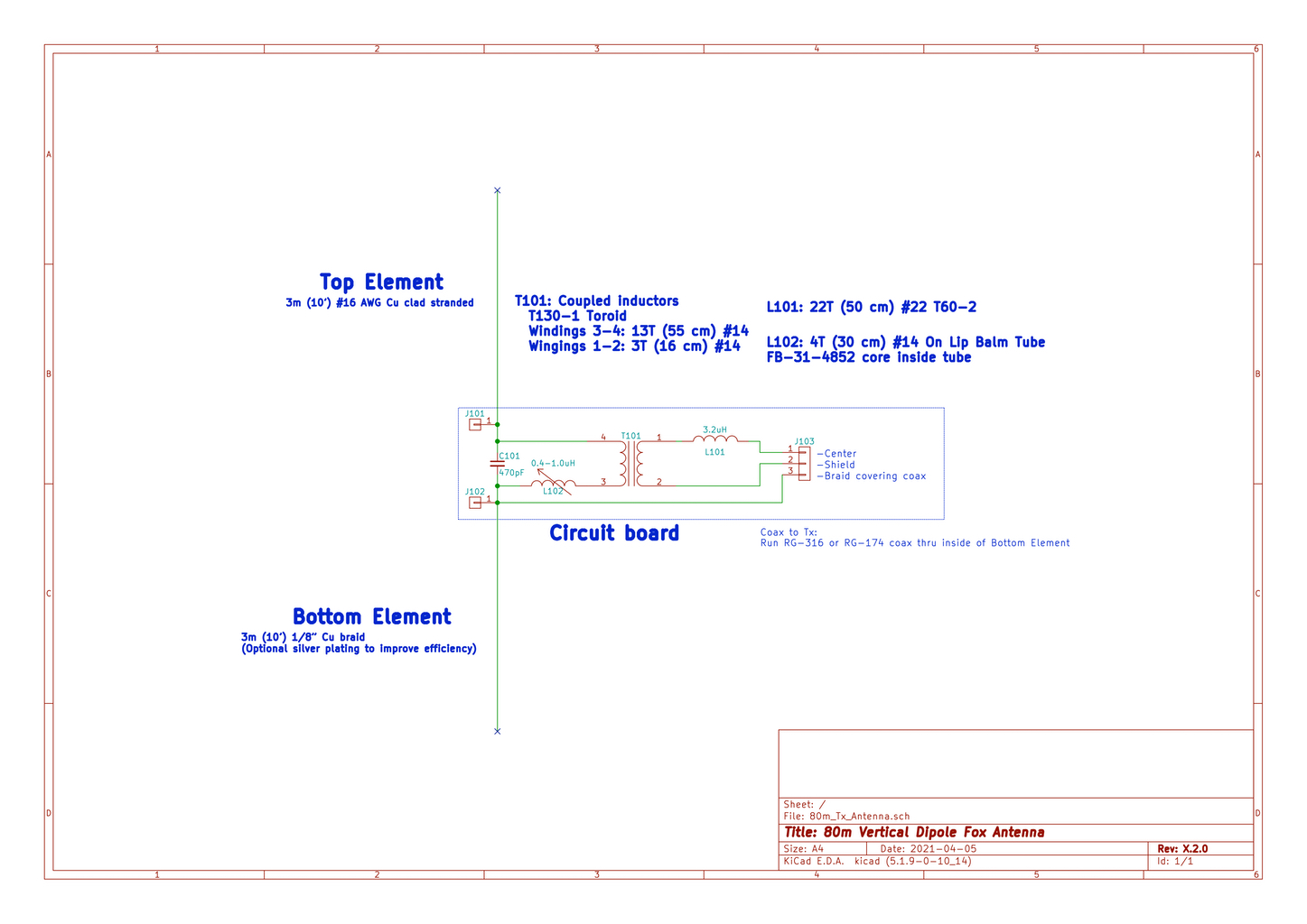
Schematic Diagram
Parts List
- 3.2m (10.5 feet) – #16 AWG or thicker stranded copper-clad antenna wire
- 3.5m (11.5 feet) – 1/8″ ID tinned copper braid – Beldon 8660 or equivalent
- 4.6m (15 feet) – RG-174 or RG-316 (preferred) coaxial cable
- 1 x T130-1 toroidal core – Amidon part #T130-1
- 1 x T60-2 toroidal core – Amidon part #T60-2
- 1 x FB-31-4852 ferrite bead – Amidon part #FB-31-4852
- 1 x 5.5ml clear empty lip balm tube (available in bulk from Amazon and others)
- 1 x 470pF Silver Mica 500V capacitor (e.g., Digi-Key)
- 1m (40 inches) – #14 AWG enameled wire
Note: 60 cm (24 in.) of Romex 14/3 solid house wiring can be used as a source of all #14 wires used in this project. The bare copper ground wire should be used for the 13 turns on T101, and the insulated wires for the 3-turn side of T101 and for L102. - 50cm (20 inches) – 22AWG enameled wire
- 12 x Nylon cable ties – 10 cm (4 in.) long, 2.5 mm wide
- 6 inches (15 cm) x 1/4-in adhesive-lined heat-shrink tubing
- 1 inch (2.5 cm) x 1/8-in adhesive-lined heat-shrink tubing
- 1 x Suitable coaxial termination connector – e.g., Cat5/Cat6 to BNC Coaxial Connector Screw Terminal
- 1 x Circuit board – KiCad Files, OSH Park (Note: this is a different board from the one used for the Ground Plane antenna!)
Construction
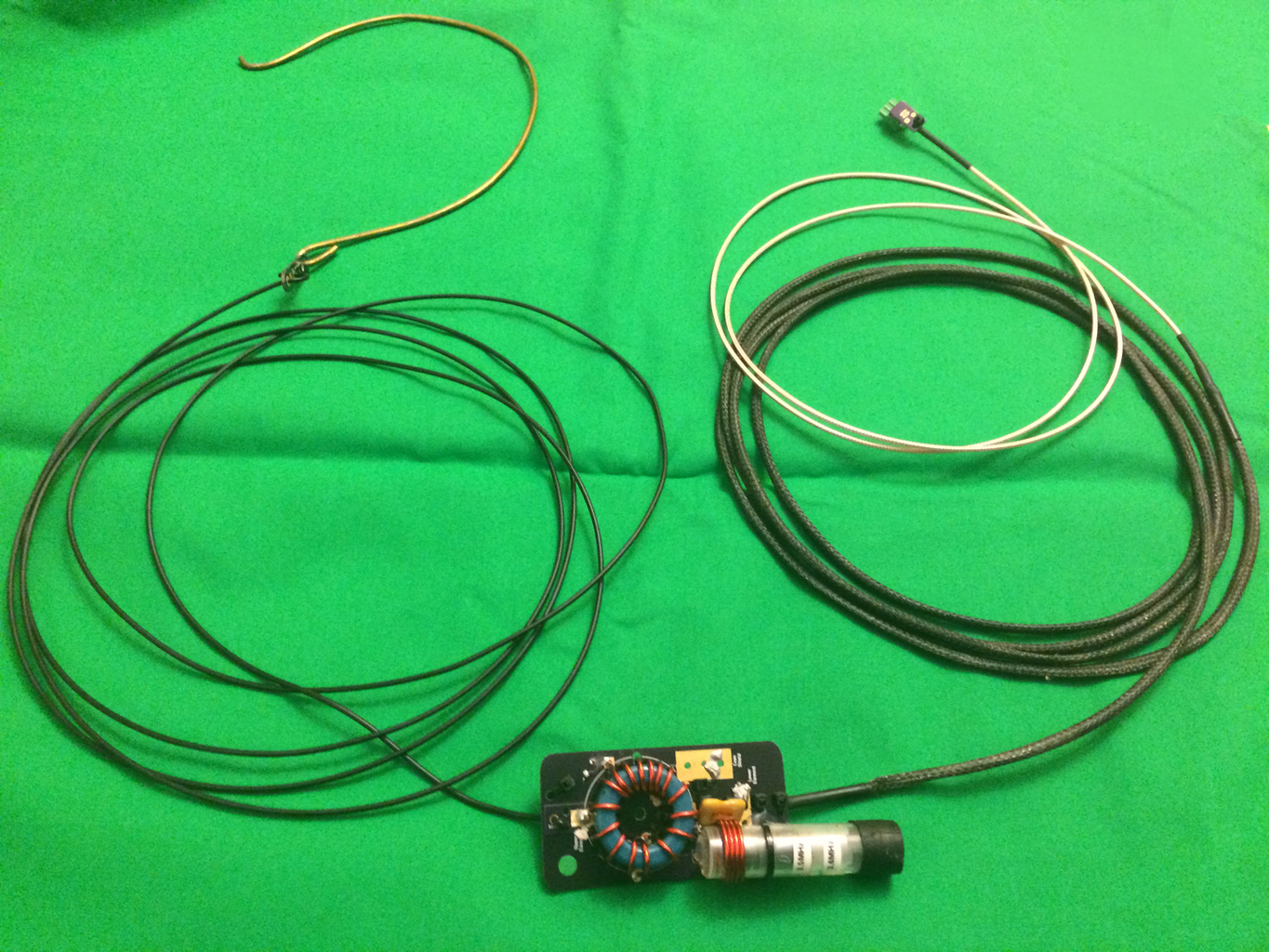
There are only four parts that make up the matching network: a transformer-like device, a fixed inductor, a variable inductor, and a capacitor. There are also two antenna elements and a coaxial feedline that meet at the network, and those require special care to provide strain relief, minimize flexure, and prevent water intrusion. So the feedpoint turns out to be a busy location despite the low parts count.
It is possible to put everything together on a standard perforated breadboard, but a custom printed circuit board is likely to result in a more reliable and reproducible antenna. An example is shown in the photos below.
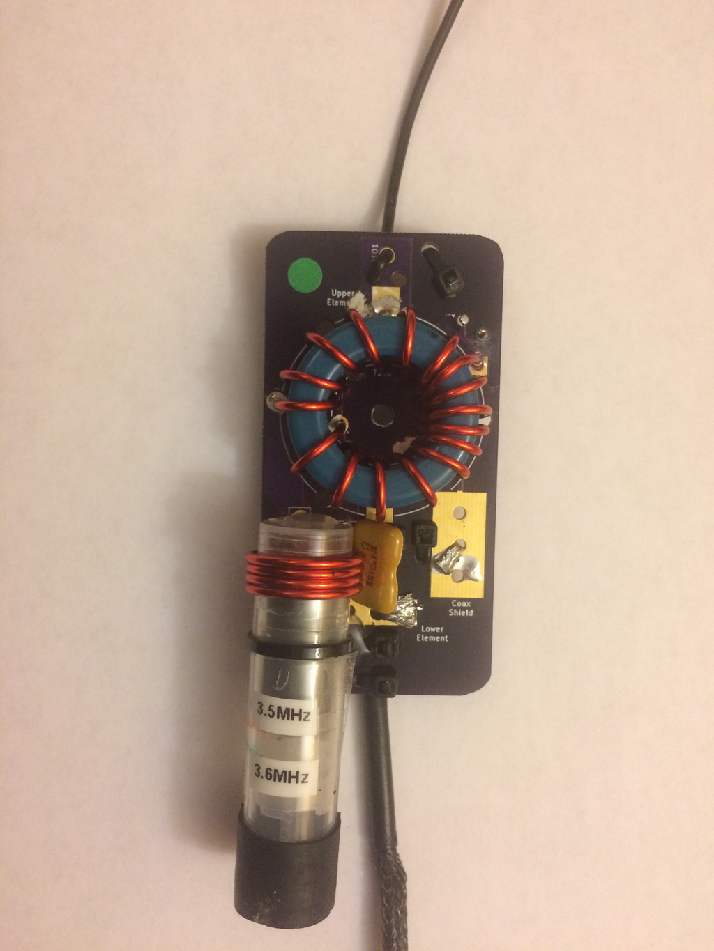
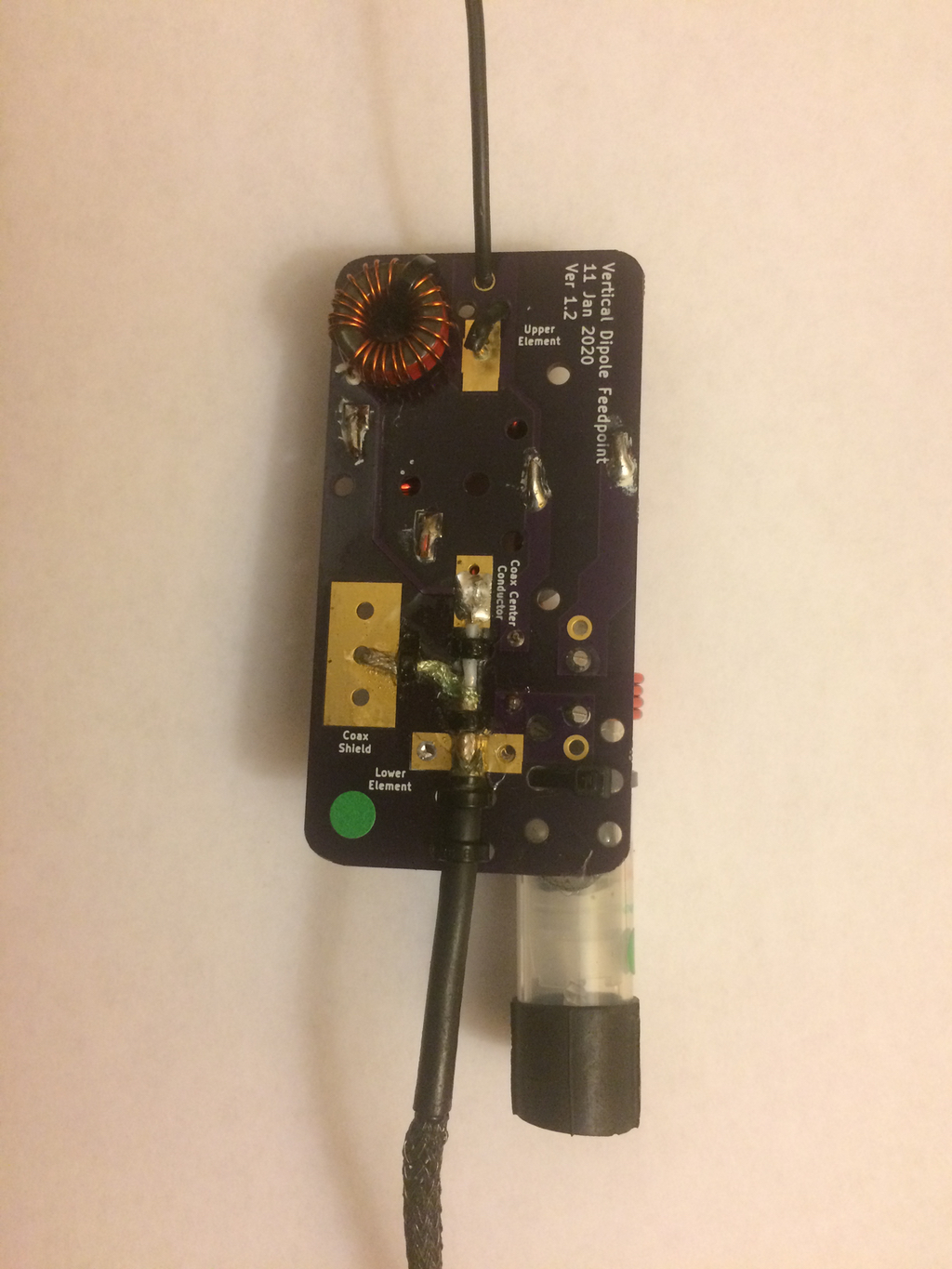
The small printed circuit board for this project is available at OSH Park. The PCB holds all the parts and provides convenient strain-relieved attachment locations for the coax and antenna wires.
Step-by-Step
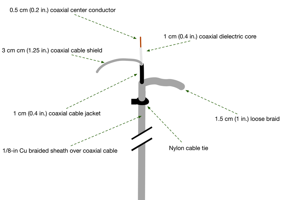
Construct the Lower Antenna Element
- Cut the 1/8-inch copper braid to length.
- Expand the copper braid to form a braided sheath. This can be done by carefully inserting a blunt rod into one end of the braid and carefully expanding the braid while avoiding snagging any of the individual braid wires. Note: this is the trickiest step of the construction process!
- Cut the coaxial cable to length.
- Insert the coaxial cable through the braided sheath.
- Secure one end of the sheath to the coaxial cable using a small cable tie, leaving 4 cm (1-5/8 in) of the coax extending beyond the end of the sheath.
- Stretch the braid along the length of coax, making the cable as snug as possible inside the sheath.
- Slide two pieces of 6 cm length adhesive-lined heat-shrink tubing over the sheath, then secure the opposite end of the sheath to the coax using another small cable tie.
Install the Lower Antenna Element
- Prepare the short protruding end of the coax for connection to the PCB as shown:
- Install the prepared coaxial cable end to the PCB by first inserting the loose braid into the plated thru-hole as shown.
- Slide one of the 3-inch lengths of adhesive-lined heat-shrink tubings up to the hole holding the braid (you may need to cut the cable tie used in construction) and shrink it using a heat gun.
- Secure the antenna element to the PCB with a cable tie through the PCB holes provided. [TODO: See photo]
- Solder the sheath, coaxial cable shield, and coaxial center conductor to their assigned locations on the PCB. [TODO: See photo]
- Stretch the braided sheath covering the coaxial cable tightly along the cable starting from the end attached to the PCB.
- Place the 1-inch length of 1/8-in adhesive-lined heat-shrink tubing over the coaxial cable and slide it halfway under the end of the braided sheath. Shrink the tubing to secure it to the outer jacket of the coaxial cable.
- Keeping the sheath stretched tight against the coaxial cable, slide the remaining 3-inch length of heat-shrink down until it just covers the 1-inch of tubing installed during the previous step and the bottom 2-1/2 inches of the sheath. Shrink the 3-inch length of tubing in place so that it covers the end of the sheath and holds it securely to the coaxial cable. [TODO: See photo]
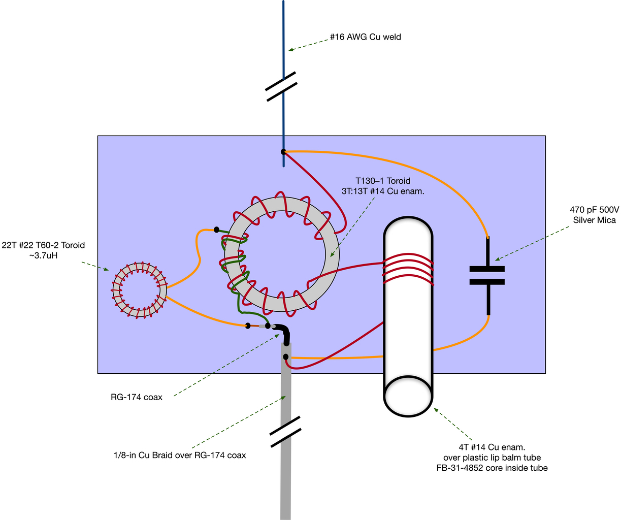
Build and Install T101
- Cut a length of 55 cm of #14 enameled wire (bare copper house wiring also works well) and use it to wind 13 turns through the T130-1 toroid core. Space the windings evenly around the core.
- Cut a length of 16 cm of #14 enameled wire (insulated copper house wiring also works) and use it to wind 3 turns through the T130-1 toroid core centering those turns on the 13 turns wound in the previous step.
- Place the wires into their corresponding holes (T101) on the PCB and cut off excess wire length, leaving 1/4-inch of wire beyond where the wires protrude through the holes. Remove T101 and carefully scrape off all the enamel insulation from where the solder will be applied. Then install T101 again on the PCB, bend its wires onto the bottom of the board, and solder.
Build and Install L101
- Cut a 50 cm length of #22 enameled wire.
- Wind the enameled wire through the T60-2 toroid core 22 turns.
- Cut off any excess wire length leaving about 1-inch of wire leads.
- Scrape off the enamel insulation from the leads using a single-sided razor blade or Exacto knife.
- Place the wires through the mounting holes for L101 on the PCB, solder in place, and trim off excess wire.
Install C101
- Place the capacitor’s leads through the mounting holes for C101.
- Bend the capacitor away from L102’s location.
- Solder the leads of C101 and trim off excess wire.
Build and Install L102
- Fully disassemble a 5.5 ml empty lip balm tube.
- Attach a FB-31-4852 ferrite bead to the adjusting base using epoxy. Carefully align the ferrite bead to the base so that once assembled the threaded rod will pass through it without interference.
- Once the ferrite bead is securely attached to the base, insert the base and bead into the tube and confirm that the bead can be easily moved up and down by turning the tube’s knob. Then seal the cap on the tube using hot glue, silicone sealant, or similar.
- Cut 30 cm of #14 enameled wire and wind it tightly around the cap end of the lip balm tube forming four (4) closely-spaced windings.
- Install the wire from the previous step into the appropriate holes on the PCB.
- The lip balm tube will be glued inside the L102 windings after initial testing of the antenna is complete. So stow it in a safe place for now.
Install the Upper Antenna Element
- Cut a 3.2m (10.5 foot) length of #16 AWG stranded antenna wire.
- Strip 1/4-inch of insulation from one end, and string it through the strain-relief hole at the top of the PCB. Push enough of the wire through the strain-relief hole so that the stripped wire reaches the plated mounting hole.
- Insert the bare stripped wire into the plated mounting hole and solder it in place, trim off any excess wire.
- Attach the snap-off PCB insulator to the end of the antenna wire, or form a small loop in the wire for attaching it to a mast.
Install the Antenna Connector
- Install an appropriate antenna connector to the end of the coaxial cable following manufacturer instructions.
Test and Calibrate the Antenna
- Insert L102’s lip balm tube into its windings on the PCB. The cap of the tube should extend beyond the end of the windings by about 5 mm. Temporarily secure the tube in place using some electrical tape.
- Turn the lip balm tube “tuning knob” until the ferrite bead is fully retracted toward the bottom of the tube.
- Suspend the antenna from the top so that it hangs vertically with the bottom antenna element between 1 cm and 50 cm above the ground.
- Connect an antenna analyzer (or transmitter and SWR meter) to the antenna’s connector.
- Set the test frequency to 3.50 MHz and measure the SWR. Note: if the antenna will be used at only one frequency, then calibration at that frequency is all that is required.
- If the SWR reading is greater than 1.5:1 lower the antenna and adjust the tuning knob slightly, then retest and repeat this step until an acceptable SWR is measured.
Note: component tolerances and construction variations can sometimes result in the antenna resonance near 3.5 MHz being unachievable. If this happens, add a 500V 20 pF fixed silver mica capacitor in parallel with C101.
The following steps are optional. Perform them if you would like to mark the approximate L102 tuning positions for antenna resonance.
- Use a permanent marker or a small piece of tape to label the location of the ferrite bead within the tube. Place the mark on the exterior of the tube. You can use the point where the ferrite bead meets the base of the lip balm tube as a reference point for placing the mark. This marks the tuning position where an acceptable SWR for 3.50 MHz is achieved.
- Repeat steps 5 through 7 for a test frequency of 3.60 MHz.
- Place labels at the tuning locations and cover them with clear packing tape if desired.
Apply Sealant
- Glue the lip balm tube inside the L102 windings using hot glue, silicone sealant, or similar. Take care to ensure that the tube is placed within the windings at the same distance as determined during testing.
- Apply a generous amount of Liquid Electrical Tape, or silicone sealant at each end of the coaxial cable where the inner conductor or braid are exposed.
- Optionally, spray the copper braid (lower antenna element) with Plasti-Dip (or similar flexible sealant) to protect it from damage and oxidation.
- Optionally, cover L102’s tuning knob using a short piece of bicycle inner tube (or similar) to prevent it from being turned accidentally during use.
Antenna Tuning
The antenna is readily adjusted to present an excellent match to any transmitter designed to operate into a 50-ohm load. Use the following steps:
- Suspend the antenna from the top so that it hangs vertically with the bottom antenna element between 1 cm and 50 cm above the ground.
- Connect an antenna analyzer (or transmitter and SWR meter) to the antenna’s connector and adjust the test frequency to any value between 3.51 MHz and 3.60 MHz.
- Adjust L102 by turning the tuning knob to achieve a minimum SWR reading.
Deployment
A long telescoping fishing rod or a young tree can be used to support the antenna as vertically as possible. The rod or tree branch needs to place the top of the antenna ~6 m (20 feet) above the ground. The author has had excellent results finding suitable trees just about anywhere in the North Carolina woods where ARDF practices have been held. A 24-foot telescoping pole with a holiday light hanger attachment has made short work of hanging antennas and makes an excellent hiking pole to boot! See the bronze tree branch hook attached to the top insulator in the photo above.
All ARDF transmit antennas (not just this design) should be placed a half-wavelength or farther away from surface water (creeks, streams, ponds, lakes, marshes, etc.) because moist ground affects radiated signal strength.
Theory of Operation
The very short dipole antenna elements provide a feedpoint impedance on the order of 2500 Ohms capacitive. Tuning the entire antenna system to resonance by the addition of loading inductors requires a large inductance (> 100 uH) which would be impractical to achieve with a sufficiently high self-resonant frequency and without high loss. So, rather than trying to resonate the entire antenna system, the approach taken here is to use a high-voltage capacitor (C101) and a variable inductor (L102) to bring the secondary of T101 to resonance. The antenna elements attached to the resonant LC circuit detune the circuit by an amount equal to the feedpoint impedance. But resonance at the operating frequency can be restored by adjusting L102 appropriately.
The primary windings (3T) of T101, and the inductance of L101 (3.2 uH), were determined empirically in order for the matching network to provide a 50-Ohm resistive load to the transmitter. The energy from the transmitter generates a high voltage across the resonant secondary circuit of T101. That voltage is limited by the losses in the wires and the cores of L102 and T101 and by the energy that “leaks” into the antenna elements and is radiated by the antenna or is lost as heat due to the resistance of the antenna wires.
Large gauge wire and hefty toroid cores help reduce resistive losses in the matching network, though such heavy-duty components are not needed to support the low power levels at which ARDF transmitters operate. The use of such beefy components enhances mechanical strength at the cost of some added weight.
The antenna is inherently inefficient, as are all the electrically short antennas used with ARDF fox transmitters. Several opportunities exist for reducing losses in this antenna. But in the wider antenna system, which includes the ground beneath the antenna, lossy ground currents swamp the other losses. So, although some improvement to overall efficiency can be realized by reducing resistive losses in the inductors and radiating elements, the antenna system will remain inefficient. Fortunately, ARDF receivers are usually no more than a few kilometers from the transmitters, and the large losses in the transmit-antenna system can be tolerated.
The transformer-like inductive coupling of the RF signal into the antenna provides a balun effect between the unbalanced feedline and the balanced dipole antenna. This should help ensure a more even current distribution between the two halves of the dipole, and less coupling to the outer shield of the coax.
The SWR bandwidth of this antenna system is about 20 kHz.
Testing thus far has indicated that the design is suitable for use in ARDF competitions. Side-by-side testing of the antenna’s radiation properties relative to typical ARDF 80m fox antenna designs has thus far shown good results. Measured signal strength is roughly equivalent to that of a matched ground plane antenna of the same length.
In testing thus far, the matching board has shown no particular sensitivity to moisture. The antenna has been used after rain and heavy dew, and no issues were noted.
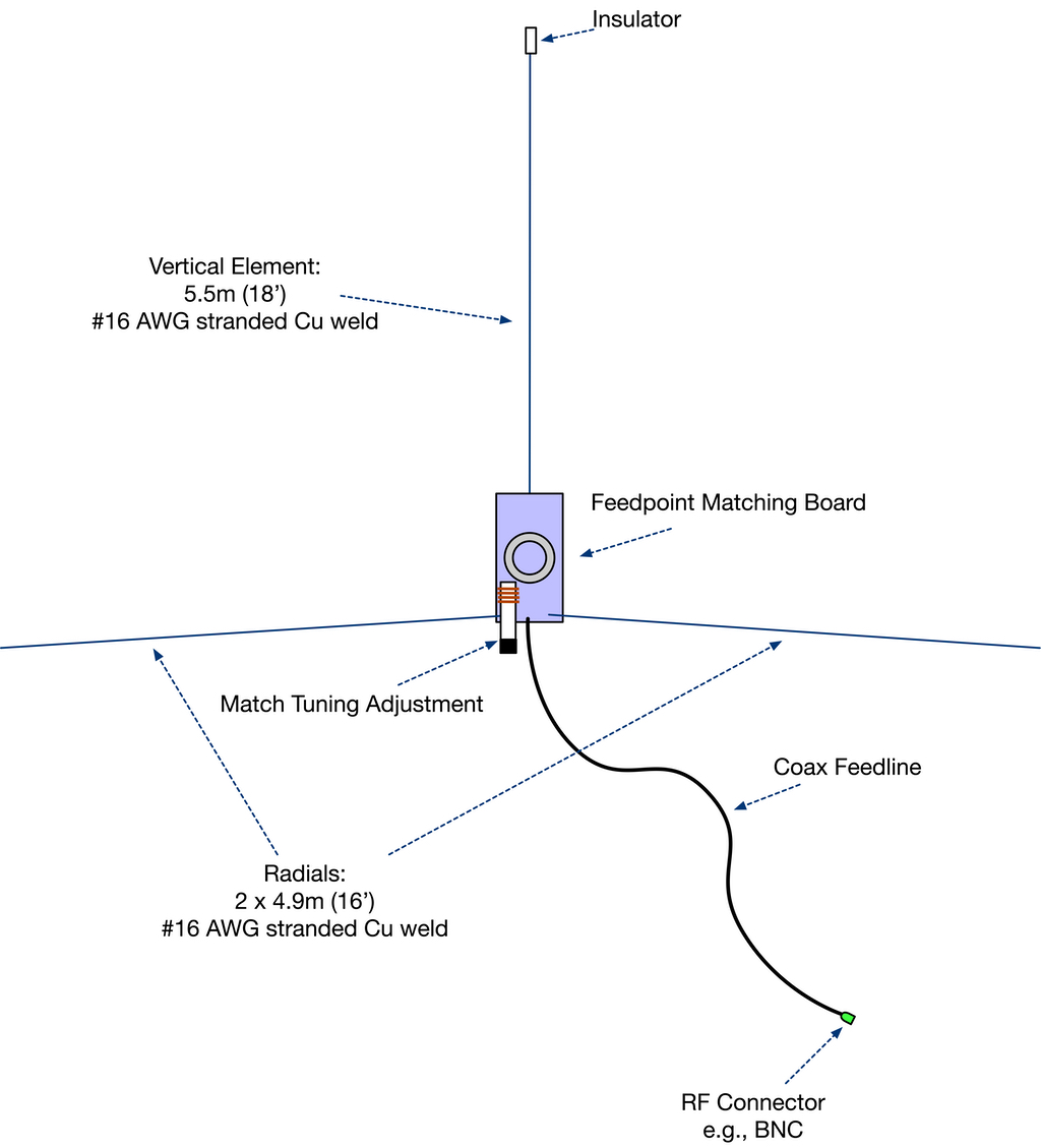
Ground Plane Antenna Design
The same tuning approach used for the Dipole can be applied to a shortened Ground Plane antenna design. The feedpoint matching circuit is nearly identical to the Dipole design, and all the same components are used. The main difference is that T101 is wired to provide an unbalanced antenna match as required for a Ground Plane antenna.
Since the Ground Plane antenna has horizontal radials there is no lower radiating element, and thus there is no need for the copper braid sheath around the coaxial cable. That difference alone makes the Ground Plane design much simpler to construct. But the radials will require more antenna wire, and thus make the ground plane antenna a bit heavier than the dipole design.
Schematic Diagram
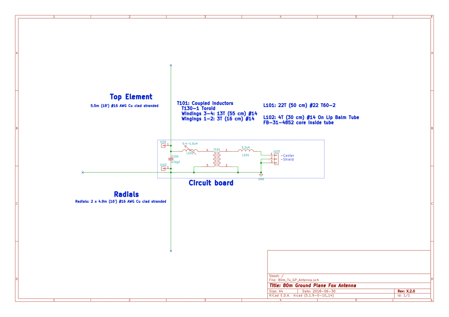 Parts List
- 16 m (52.5 feet) – #16 AWG or thicker stranded copper-clad antenna wire
- 1 x T130-1 toroidal core – Amidon part #T130-1
- 1 x T60-2 toroidal core – Amidon part #T60-2
- 1 x FB-31-4852 ferrite bead – Amidon part #FB-31-4852
- 1 x 5.5ml clear empty lip balm tube (available in bulk from Amazon and others)
- 1 x 470pF Silver Mica 500V capacitor (e.g., Digi-Key)
- 1m (40 inches) – #14 AWG enameled wire
Note: 60 cm (24 in.) of Romex 14/3 solid house wiring can be used as a source of all #14 wires used in this project. The bare copper ground wire should be used for the 13 turns on T101, and the insulated wires for the 3-turn side of T101 and for L102. - 50cm (20 inches) – #22 AWG enameled wire
- 12 x Nylon cable ties – 10 cm (4 in.) long, 2.5 mm wide
- 1 x Suitable coaxial termination connector – e.g., Cat5/Cat6 to BNC Coaxial Connector Screw Terminal
- 1 x Circuit board – OSH Park (Note: this is a different board from the one used for the Dipole antenna!)
Construction
Construction of the Ground Plane design is identical to the steps described for the Dipole antenna with these changes:
- Omit the construction and installation steps for the lower antenna element.
- Connect two 16-foot #16 wires to function as the Ground Plane’s radials.
Deployment
A long telescoping fishing rod, or a young tree, can be used to support the antenna as vertically as possible. The rod or tree branch needs to place the top of the antenna ~6 m (20 feet) above the ground. The radials should be spread out along the ground in opposite directions. Stake the radials down, or clearly mark them, to avoid having ARDF competitors trip over them!
If a telescoping fishing rod is used, the feedpoint PCB could be attached (by electrical or duct tape) just above the bottom end of the pole. This should help keep the PCB from dangling, reducing stress on the fishing rod.
All ARDF transmit antennas (not just this design) should be placed a half-wavelength or farther away from surface water (creeks, streams, ponds, lakes, marshes, etc.) because of the effect of the moist ground on radiated signal strength.
Other Experimentation
Readers are encouraged to experiment with improvements to the design. Let us know what you come up with!
Improved Antenna Efficiency: Efficiency could be improved, if desired, by substituting silver-plated braid for the tin-plated braid used for the lower radiating arm, larger diameter copper wire for the upper radiating arm, and a lower-loss toroid core. The improved efficiency would come at the cost of increased weight and material costs. Increasing the lengths of the radiating elements will also improve efficiency, but will result in a taller antenna. Tweaking of the toroid windings and matching inductor may be necessary if the antenna is lengthened considerably.
Feedline Loss: Using a lower-loss feedline would improve efficiency, but only marginally. Loss through the specified 4.6 meters (15 feet) of RG-174 coax at 3.6 MHz is only about 0.2 dB. At the QRP transmit power levels used for ARDF the RG-174 is just fine. The weight savings of the thin coax is worth the small cost in power loss.