
Note: I invested a good deal of time and effort attempting to improve the performance of the R3500D kit and never obtained the consistent results I hoped for. Then I discovered that the factory-built R3500D (not the kits) has an updated design and improved performance. Then I discovered that a factory-assembled R3500D can be purchased online (at Taobao.com) for less than I paid for the modifications to the kit!
At that point, I lost interest in the mods. The R3500D page has been updated with information on the performance of the factory-built units.
If you are determined to get your R3500D kit to work better, below are some ideas for improving the R3500D kit. Don’t apply the cardioid improvements to a factory-built unit – the factory-built R3500D doesn’t need the cardioid mods.
1. Cardioid Improvements
A cardioid pattern with a small front-to-back ratio (i.e., a subtle difference between max and min) makes it difficult to use an 80m receiver effectively. So improving the R3500D’s cardioid f/b ratio should make the receiver easier to use, and more effective as an ARDF tool.
For under $10 and a couple of hours of work, it is possible to give the R3500D a distinct cardioid pattern. Testing and tweaking are still going on as of this writing, but already the design can provide a cardioid pattern similar to some units costing many times more. What has not yet been proven is how robust the pattern is over temperature and vibration. More units will need to be modified and tested before the final verdict is in.
Modification Description
A PCB to hold all the parts (except T102 and R101) is available at OSH Park.
The required modification steps are as follows:
- Remove the batteries from the R3500D.
- Disassemble the chassis of the R3500D, removing all retaining screws and the screw holding the telescoping antenna to the PCB. Then remove the R3500D PCB from the chassis. (You may leave the red and black power leads in place.)
- Remove R1 from the R3500D PCB, and clean any remaining solder blocking the R1 mounting holes on the PCB.
- Lift the lead of C1 that is connected to L1, and leave the lead disconnected for now. Clean any remaining solder blocking the empty C1 mounting hole on the PCB.
- On the bottom of the R3500D PCB cut the trace between the telescoping antenna and the sense switch S1.
- Construct the combiner T102. [TODO: Picture and details.]
- Glue the combiner T102 to the R3500D PCB just above S1 and to the right of T1. Combiner wires should exit T102 in the direction of the ferrite rod antenna.
- Connect one combiner input (pin 1) to the C1 mounting hole that was vacated in step 4, and solder in place.
- Connect the other combiner input (pin 3) to the R1 mounting hole leading to the trace connected to sense switch S1.
- Connect the combiner output (pin 2) to C1’s disconnected lead.
- Install R101 on the back of the R3500D PCB. Take care not to place it where it will interfere with the whip antenna when it is replaced. [TODO: Picture and details.]
- Construct T101. [TODO: Picture and details.]
- Populate the modifications daughter board with T101, C101, and C102. Note: omit RV101 – it is not used.
- Set the modifications daughter board in place on top of the R3500D PCB, and mark the position for the through-hold for the ground wire. Then drill a 3/32″ hole at the marked location. [TODO: Picture to be added.]
- Connect the R3500D PCB ground to the daughter board ground with a short piece of wire, running the wire through the hole drilled in the previous step.
- Set the modifications daughter board in place on top of the R3500D PCB, and attach it using the screw for the telescoping antenna.
- Attach a short wire between P101 (pin 1) and sense switch S1 (pin 2 – that’s the pin closest to the ferrite rod antenna). Tack solder the wire directly to S1 pin 2.
- Install batteries and headphones to the R3500D, fully extend the telescoping antenna, and tune to a nearby vertically-polarized 80m signal source located at least 10m away.
- Adjust CT1 and T1 for the maximum received signal (S1 is not pressed).
- Press and hold S1, rotate the R3500D so that it is oriented with the PCB component-side facing the signal source, then adjust C101 for a minimum signal. (If a sufficiently-weak signal cannot be achieved, shorten the telescoping antenna by 5 cm.)
- Repeat the previous two steps until you are satisfied with the cardioid performance and sensitivity of the figure-8 pattern.
- Re-assemble the R3500D.
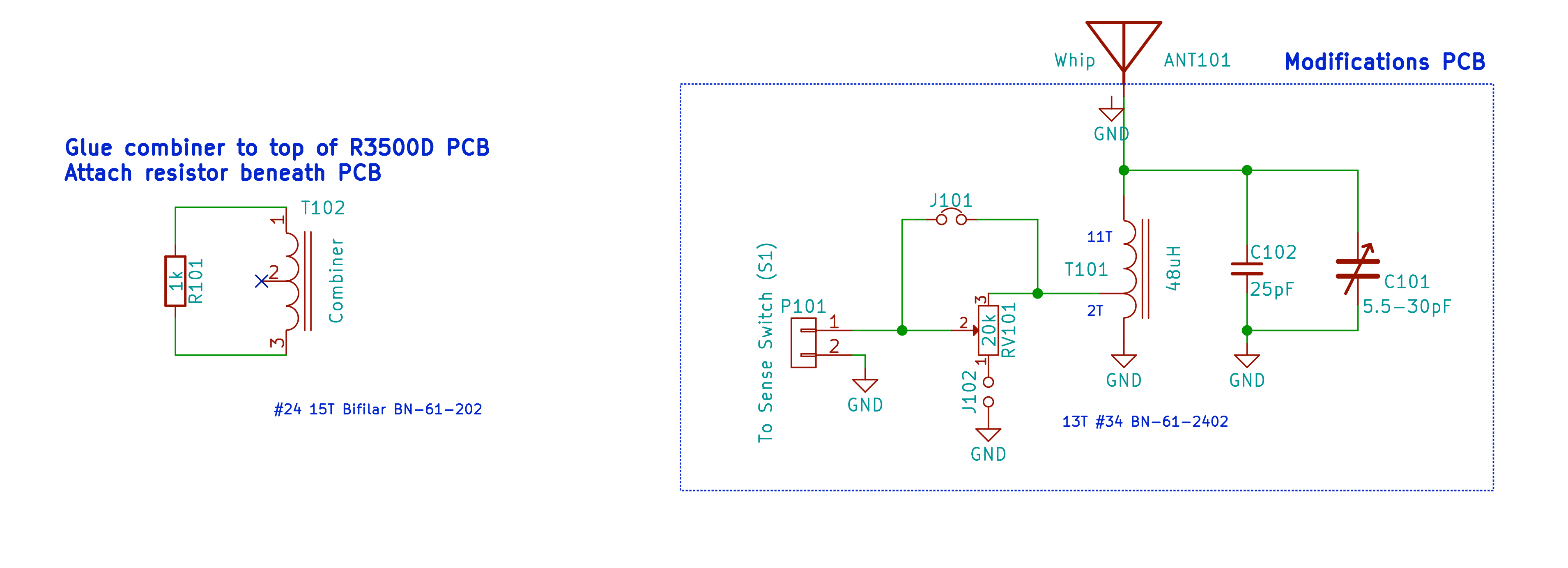
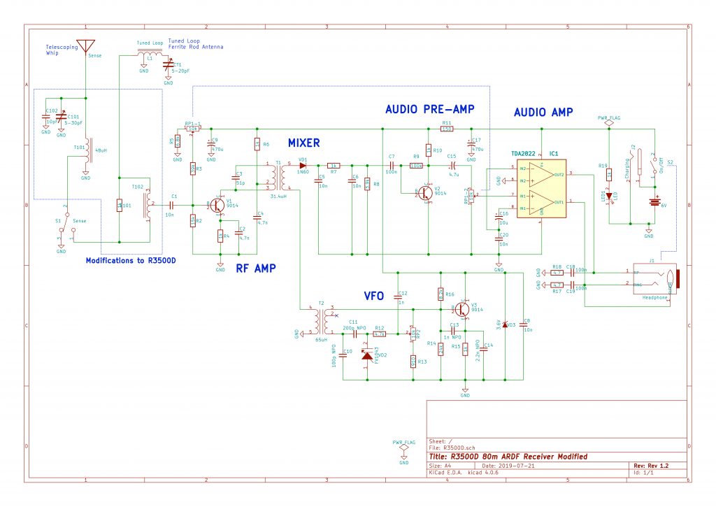
With the cardioid modifications in place, the R3500D schematic looks like the following diagram. Modifications are inside the blue polygon at the upper left of the schematic.
Circuit Description
The modifications described above affect the sense antenna and the coupling between the sense antenna and the tuned-loop.
Components C101, C102, and T101 together with the telescoping whip implement a tuned sense antenna. The tap on T101 couples loosely to it so as to avoid excessively loading the tuned circuit. By adjusting C101 to bring the antenna circuit near resonance, the proper amount of phase shift can be achieved.
The height of the telescoping whip adjusts the amplitude of the sense signal reaching the combiner, allowing it to be matched with the amplitude of the tuned-loop antenna to achieve a distinct cardioid receive pattern.
Using the coupler between the sense and the tuned-loop is important. Without it, the interaction between the tuned sense antenna and the tuned loop makes it very difficult to achieve a reliable cardioid pattern.
2. Shield Diodes from Light
The glass-shell diodes (VD1, VD2, and VD3) are sensitive to light. Their properties, in particular the capacitance across VD2, vary depending on the amount of external light reaching the diodes. The most obvious negative effect from the diode light sensitivity is that the frequency setting jumps in response to changes in ambient light conditions.
The problem is readily solved by covering each of the diodes with an opaque substance. Anything opaque and non-conductive will do the job. A dab of opaque glue, paint, or putty fully covering each diode, should work just fine.
3. Reverse Rose Compass
Any ARDF receiver, especially those for use by beginners, should include a reverse rose compass. An attached reverse-rose compass is mandatory because it greatly simplifies taking signal bearings.
A compass platform is easily added to the R3500D. Wood or some other non-magnetic substance is a good choice for platform material. The ideal size for a platform is roughly 3 cm x 20 cm x 1 cm. A thinner platform is better provided that it is sufficiently strong. Home improvement stores sell wooden shims that happen to be just the right size.
The platform mounts readily to the top of the R3500D chassis as shown in the photo below. M3-.5 machine screws with matching nuts and washers were used to attach the wooden shim to the front shell of the chassis only. There is enough extra space inside the chassis that the screw ends do not interfere with the ferrite rod antenna. Avoid drilling holes that pass through the latch area at the top center of the chassis. Also, take care to locate the platform so that it avoids the telescoping antenna.
Glue could be used instead of, or in addition to, screws for affixing the platform.

Once the compass platform is attached, it is time to install the compass. Compasses of reasonable quality for under $10 are available. So far I’ve been pleased with a Boy Scout model available online. The compass mechanism is readily detached from the base (if desired) to minimize confusion and reduce compass overhang of the compass platform. Leaving the compass inside the base would be OK too, but I didn’t want to allow the declination to be set. Zero degrees should always be aligned with the ferrite rod axis. If the compass declination is made adjustable then it will be possible for the user to misalign the compass.
[TODO: Add a close-up picture of attached compass]
White caulk or silicone sealant works well for attaching the compass to the wooden platform. Use a generous amount to create a uniform white background for easy viewing of the red compass needle. Glue the compass close to the far end of the platform, and allow several days for the adhesive to fully dry.
4. Attenuator Knob Calibration
It is important for an ARDFer to calibrate the attenuation knob to indicate the distance to the transmitter. A white dial face to go behind the attenuation knob makes the calibration easy.
[TODO: add picture of installed dial face]
A white dial face is easily constructed using plain white paper, scissors, and some clear packing tape. Cut out a paper circle of the right size, apply clear packing tape to both sides and cut off any excess. Cut a small hole in the center of the circle just large enough to fit over the potentiometer shaft. Remove the knob and retaining nut from the attenuation potentiometer. Slide the white disk onto the shaft, and replace the retaining nut to hold it in place. Then replace the knob.
[TODO: provide a template for printing]
Mark the white dial face using a fine-tip permanent marker. Place lines on the dial face where the transmitter is heard at your preferred volume level while standing 50 meters, 100 meters, and 500 meters from the transmit antenna. The lines can be removed using rubbing alcohol when it comes time to recalibrate for a different transmitter or transmit antenna configuration.