There is still plenty of work to be done on the software, but it is functional as a basic dual-band receiver, and potentially useful for others. So I’ve cleaned it up, added the MIT License language as a header to each file, and posted it all on GitHub: https://github.com/DigitalConfections/Receiver-Development-Platform
I will continue to update the software as regularly as I can, especially since I will be using git (and the GitHub repository) for configuration management and archiving.
Licensing is the least restrictive that I could find. You can pretty much do anything you want to with it. Enjoy! But if you identify ways to improve it, I would much appreciate it if you would submit your improvements to the project.
The linear power regulators have been installed and tested on the Receiver board, along with the PCF8574A I2C port expander IC. A simple driver for the port expander was written and shown to work to control and read the port expander pins. The SA605 receiver IC was installed, along with the filters and supporting components. The Digital Interface board was then plugged into the Receiver, and the entire system of three boards was powered up and tested.
The receiver now operates on 2 meters: the Control Head allows the receiver’s operating frequency to be set, and the received signal strength is shown on the display. The receiver itself is lacking in sensitivity, but it does receive strong signals injected into the matching circuit connected to the SA605 input.
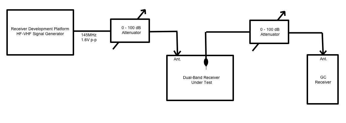
Lacking an oscilloscope, the following test set-up will be used to investigate and tweak the receiver sensitivity:
Receiver Test Set-up Diagram
Click on the above image for a closer look. The original Receiver Development Platform experimental boards (built several months ago) will be used as a precision VHF signal generator. An adjustable 100dB attenuator will allow precise control over the signal level delivered to the receiver under test by the signal generator. Instead of probing test points using an oscilloscope, a VHF all-mode receiver will be used; its RF input attenuated by a second adjustable attenuator. It is hoped that this will allow very low signal levels to be generated, and probed at board level. The receiver’s S-meter will provide a rough estimate of the absolute signal levels, while the precision attenuators should provide a way to obtain reasonably-accurate measurements of changes in signal strength.
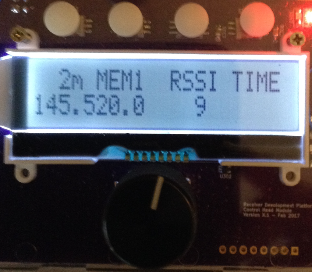
A rudimentary linkbus is now in place, allowing the Control Head and the Digital Interface to exchange information with one another. The two recognize when the other device is sharing the bus, and behave accordingly. When connected to a Digital Interface, the Control Head displays a special dual-band receiver screen that shows a (growing) number of receiver settings and related information. Below is a picture of the receiver display as it stands right now:
Receiver Display for 145.52 MHz
The four white dots across the top of the above image are the menu buttons. Immediately below the buttons, printed across the top row of the LCD, are labels indicating the current function assigned to each button: Button 1 sets the band (it is currently set to 2 Meters), Button 2 sets the active memory location (currently memory Location #1), Button 3 sets the received signal parameter (currently Radio Signal Strength), and Button 4 sets the auxiliary function (currently Time of Day). Below the button labels is receiver information: the receiver is currently set to 145.5200 MHz, the received signal strength is 9, and the time is not yet implemented (blank).
Just below the display is the knob of the rotary encoder. Depressing the rotary encoder knob activates another switch. A long press (>3 seconds) on the knob enters the Frequency Edit mode, and a blinking cursor appears (see below) indicating the digit to be incremented (or decremented) by turning the dial. Tapping the knob advances to the next digit; turning the knob changes the value of the digit. Frequency Edit mode is exited by another long press on the knob, or simply by taking no action for 5 seconds.
Editing a 2m Frequency
The * next to the MEM4 label in the image above indicates that the frequency has been changed, and now differs from what is stored in memory Location 4. The frequency setting can be saved to MEM4 by pressing and holding the MEM4 key for about 3 seconds. Changing to a different memory location (by tapping the MEM4 button) will lose any changes made to the frequency setting. Each band has its own set of five memory locations.
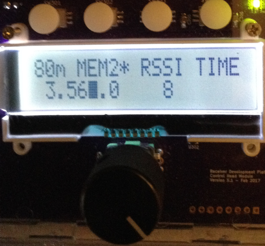
The image below shows an 80m memory location being edited, with the kHz digit being changed.
Editing an 80m Frequency
Although a signal strength is indicated, there is no analog radio circuitry built yet. The correct VFO and BFO signals are being set in the Si5351, and the audio gain level can be adjusted, but the receiver itself is still absent. The RSSI is just noise at the ATmega328 ADC input, but it is a real value being measured and reported by the Digital Interface and being sent to the Control Head over the linkbus. This should make for a convenient test platform for the Receiver board, which will get populated next. And once the Receiver board is working we will have a functional, if simple, ARDF receiver.
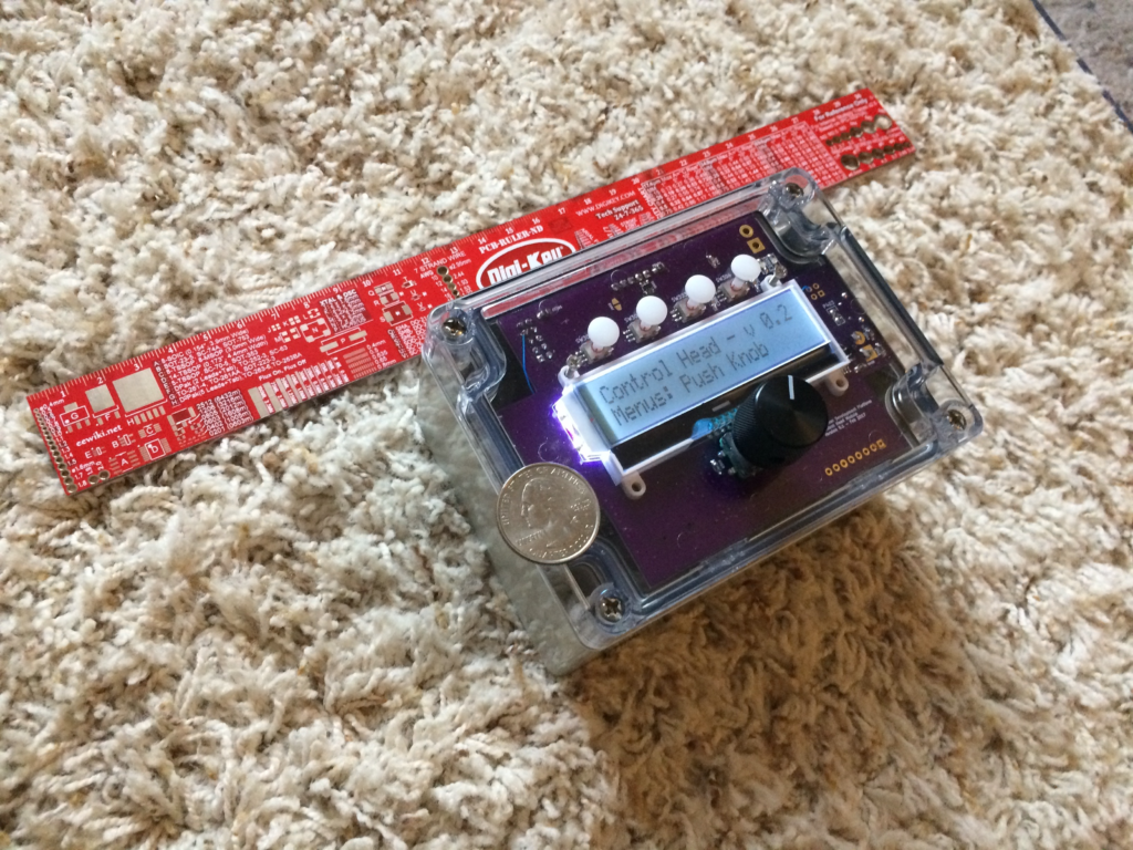
There has been a good deal of progress on both the hardware and software fronts. Button “plungers” of the proper length arrived, along with nuts and bolts (2mm size) to retain the display in the transparent lid, so it is now possible to see how a Control Head will look:
The ruler and quarter provide a sense of scale: the box is easily held in one hand, but it fills the hand. The box is large enough to hold the entire 2-band receiver, and a battery. The four white dots are the button plungers mentioned above, and serve as the “menu” buttons. The black knob below the display operates the rotary encoder, which can be pressed to activate a fifth button.
Firmware now includes a linkbus (inter-processor communication), allowing the Control Head to communicate with and control the Digital Interface, and thus the receiver. The Receiver board has not yet been populated.
The Control Head can now instruct the Digital Interface to fully configure the Si5351 clock chip, set the main volume, the tone volume, and report ADC readings. We are getting close to having a platform that can support receiver debugging and testing.


 The ruler and quarter provide a sense of scale: the box is easily held in one hand, but it fills the hand. The box is large enough to hold the entire 2-band receiver, and a battery. The four white dots are the button plungers mentioned above, and serve as the “menu” buttons. The black knob below the display operates the rotary encoder, which can be pressed to activate a fifth button.