
This post concerns the Open ARDF Equipment Project, which is utilizing the Receiver Development Platform, both of which are being developed together.
The linear power regulators have been installed and tested on the Receiver board, along with the PCF8574A I2C port expander IC. A simple driver for the port expander was written and shown to work to control and read the port expander pins. The SA605 receiver IC was installed, along with the filters and supporting components. The Digital Interface board was then plugged into the Receiver, and the entire system of three boards was powered up and tested.
The receiver now operates on 2 meters: the Control Head allows the receiver’s operating frequency to be set, and the received signal strength is shown on the display. The receiver itself is lacking in sensitivity, but it does receive strong signals injected into the matching circuit connected to the SA605 input.
Lacking an oscilloscope, the following test set-up will be used to investigate and tweak the receiver sensitivity:
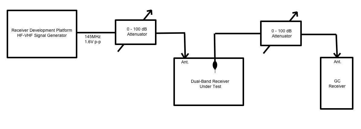
Click on the above image for a closer look. The original Receiver Development Platform experimental boards (built several months ago) will be used as a precision VHF signal generator. An adjustable 100dB attenuator will allow precise control over the signal level delivered to the receiver under test by the signal generator. Instead of probing test points using an oscilloscope, a VHF all-mode receiver will be used; its RF input attenuated by a second adjustable attenuator. It is hoped that this will allow very low signal levels to be generated, and probed at board level. The receiver’s S-meter will provide a rough estimate of the absolute signal levels, while the precision attenuators should provide a way to obtain reasonably-accurate measurements of changes in signal strength.