This post concerns the Open ARDF Equipment Project, which is utilizing the Receiver Development Platform, both of which are being developed together.
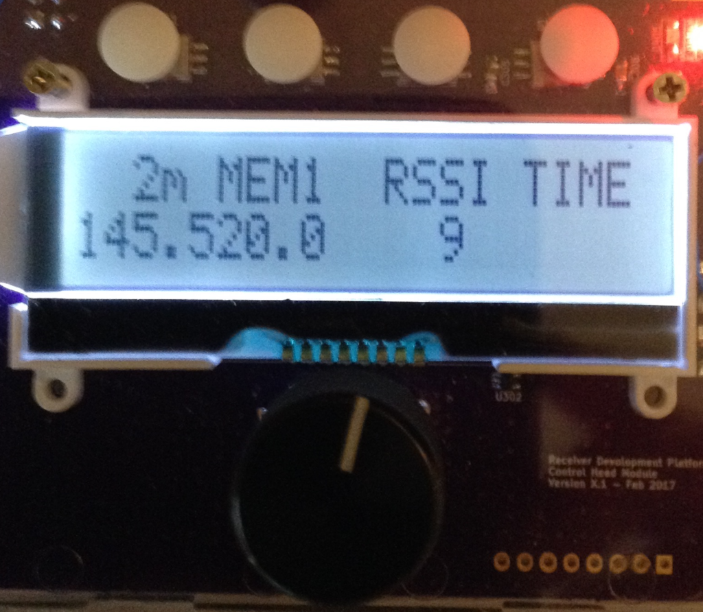
A rudimentary linkbus is now in place, allowing the Control Head and the Digital Interface to exchange information with one another. The two recognize when the other device is sharing the bus, and behave accordingly. When connected to a Digital Interface, the Control Head displays a special dual-band receiver screen that shows a (growing) number of receiver settings and related information. Below is a picture of the receiver display as it stands right now:

The four white dots across the top of the above image are the menu buttons. Immediately below the buttons, printed across the top row of the LCD, are labels indicating the current function assigned to each button: Button 1 sets the band (it is currently set to 2 Meters), Button 2 sets the active memory location (currently memory Location #1), Button 3 sets the received signal parameter (currently Radio Signal Strength), and Button 4 sets the auxiliary function (currently Time of Day). Below the button labels is receiver information: the receiver is currently set to 145.5200 MHz, the received signal strength is 9, and the time is not yet implemented (blank).
Just below the display is the knob of the rotary encoder. Depressing the rotary encoder knob activates another switch. A long press (>3 seconds) on the knob enters the Frequency Edit mode, and a blinking cursor appears (see below) indicating the digit to be incremented (or decremented) by turning the dial. Tapping the knob advances to the next digit; turning the knob changes the value of the digit. Frequency Edit mode is exited by another long press on the knob, or simply by taking no action for 5 seconds.

The * next to the MEM4 label in the image above indicates that the frequency has been changed, and now differs from what is stored in memory Location 4. The frequency setting can be saved to MEM4 by pressing and holding the MEM4 key for about 3 seconds. Changing to a different memory location (by tapping the MEM4 button) will lose any changes made to the frequency setting. Each band has its own set of five memory locations.
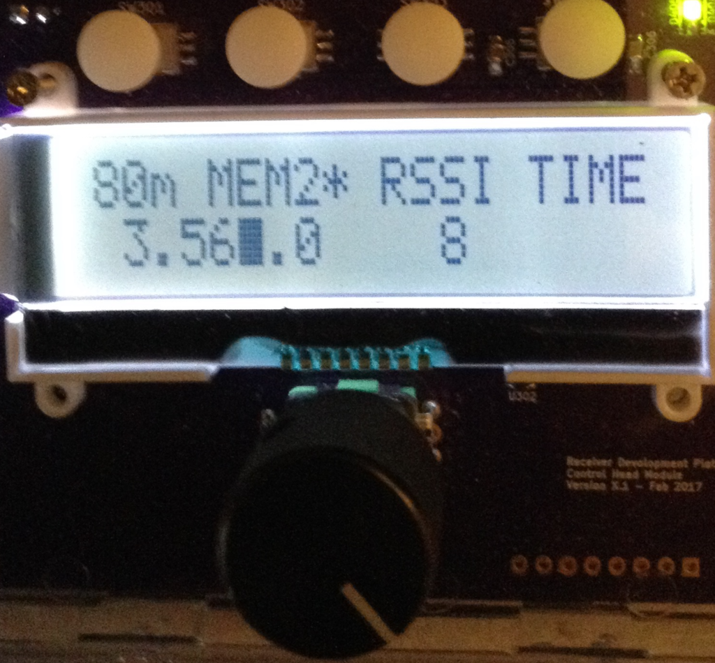
The image below shows an 80m memory location being edited, with the kHz digit being changed.

Although a signal strength is indicated, there is no analog radio circuitry built yet. The correct VFO and BFO signals are being set in the Si5351, and the audio gain level can be adjusted, but the receiver itself is still absent. The RSSI is just noise at the ATmega328 ADC input, but it is a real value being measured and reported by the Digital Interface and being sent to the Control Head over the linkbus. This should make for a convenient test platform for the Receiver board, which will get populated next. And once the Receiver board is working we will have a functional, if simple, ARDF receiver.
